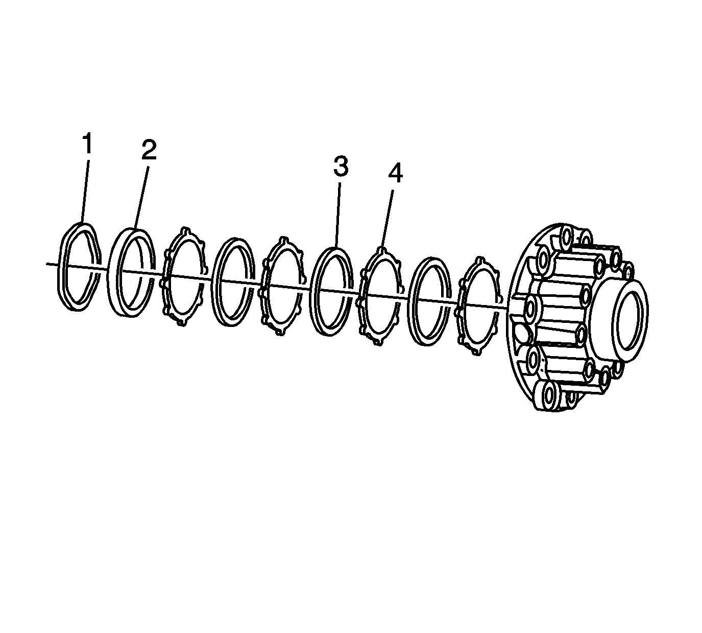
Important: Friction discs and separator plates develop specific wear patterns. During disc and plate installation, the components must be installed in the specific order in which they were removed.
- Install the right clutch pack to the right case.
| • | Install the separator plates (4). |
| • | Install the friction discs (3). |
| • | Install the friction disc (thick) (2). |
| • | Install the bellville washer (1). |
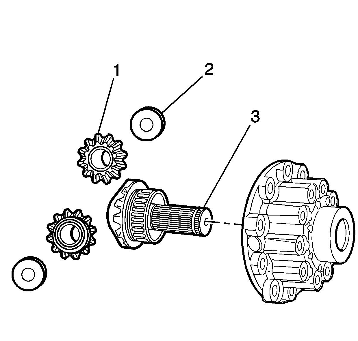
- Install the right output shaft and gear (3), side gears (1), and
washers (2) to the right differential case.
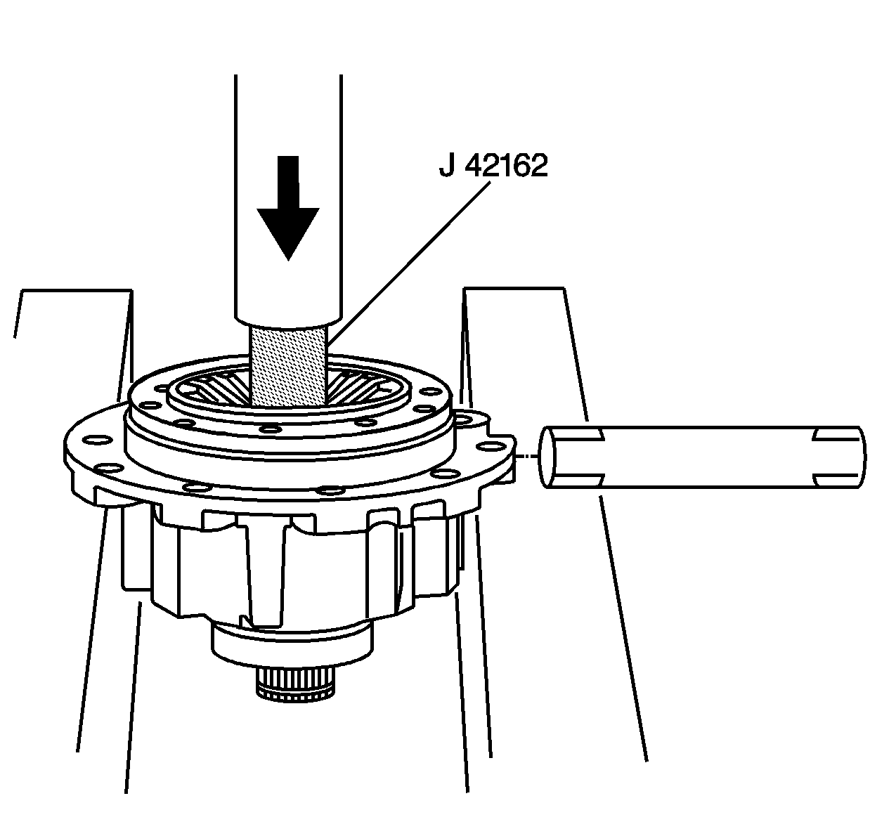
- Using the
J 42162
and a hydraulic press, compress the bellville washer and clutch
pack in order to install the cross pin to the right differential case.
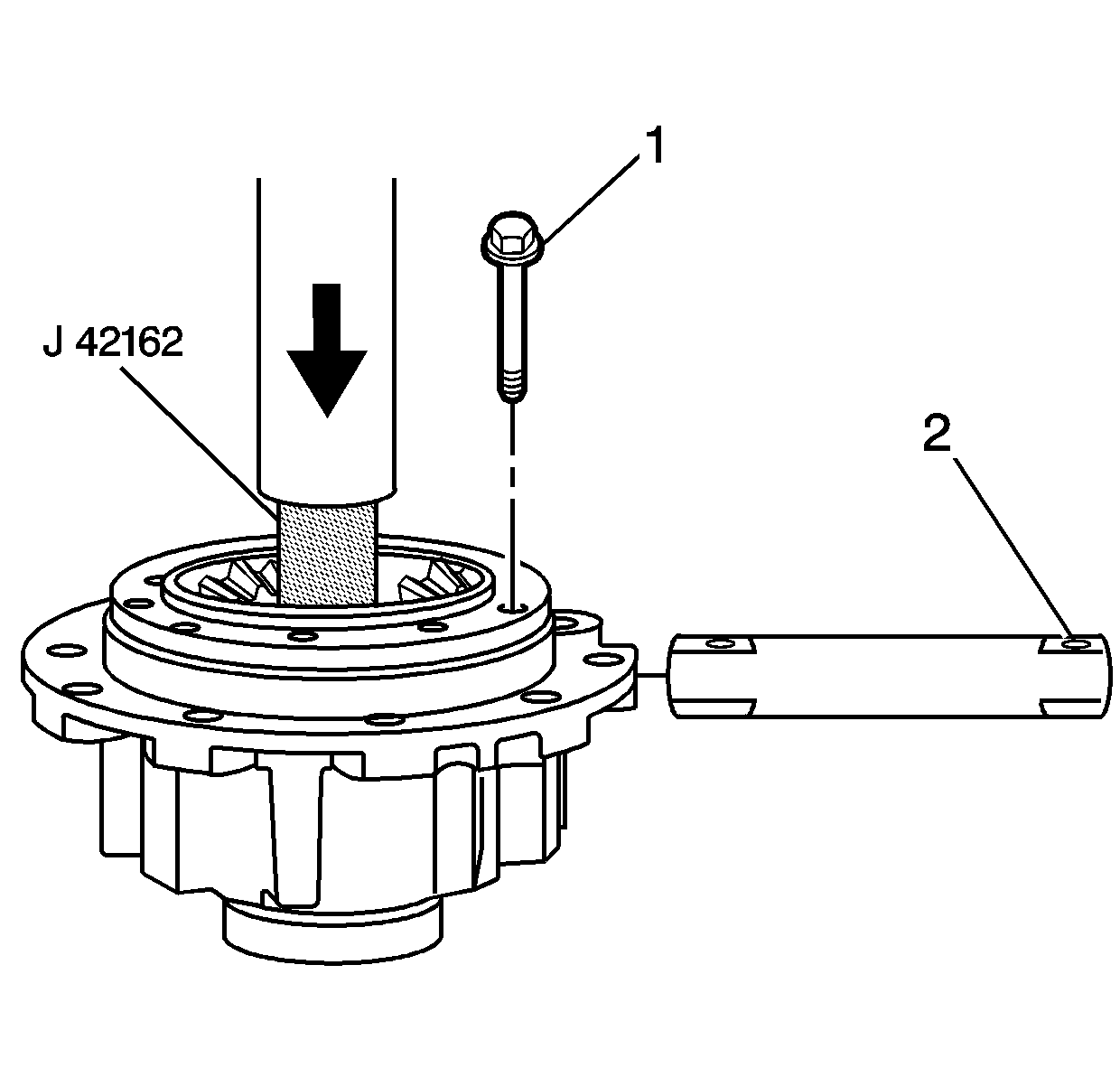
- Using an M8 bolt for alignment, properly position the cross pin into the right differential case. The hole
in the pin (2) must align with the hole in the case. During final assembly of the case halves, the pin retaining bolt (1) must be able to pass through the hole in the cross pin.
- With the pin and case aligned, release the pressure from the press and remove the
J 42162
and bolt.
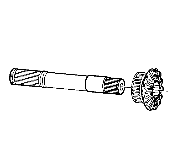
- Install the gear to the left intermediate shaft.
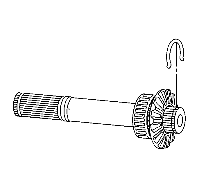
- Install the C-clip to the left intermediate shaft.
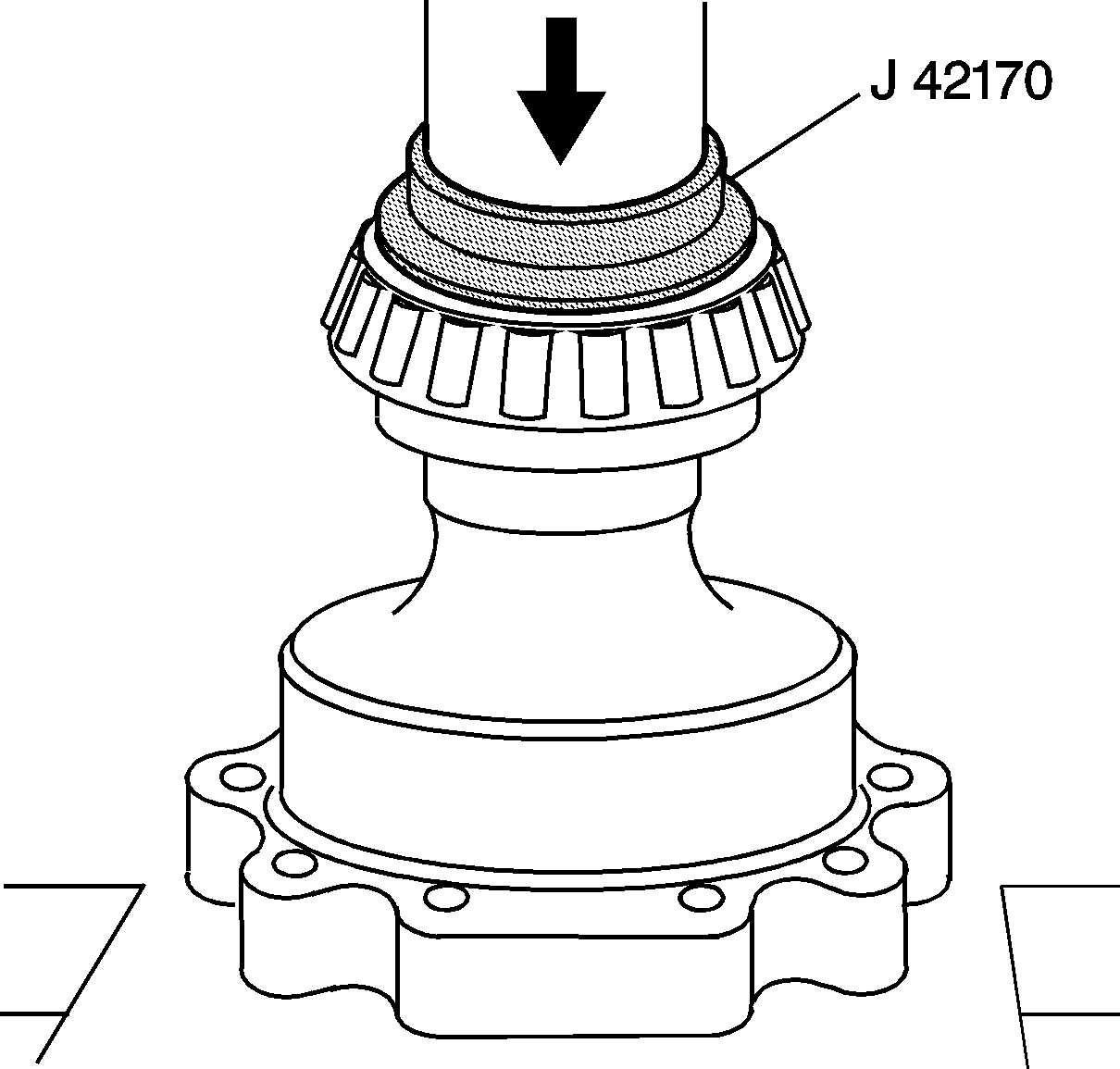
- Using the
J 42170
and a hydraulic press, install the
left side bearing to the differential.
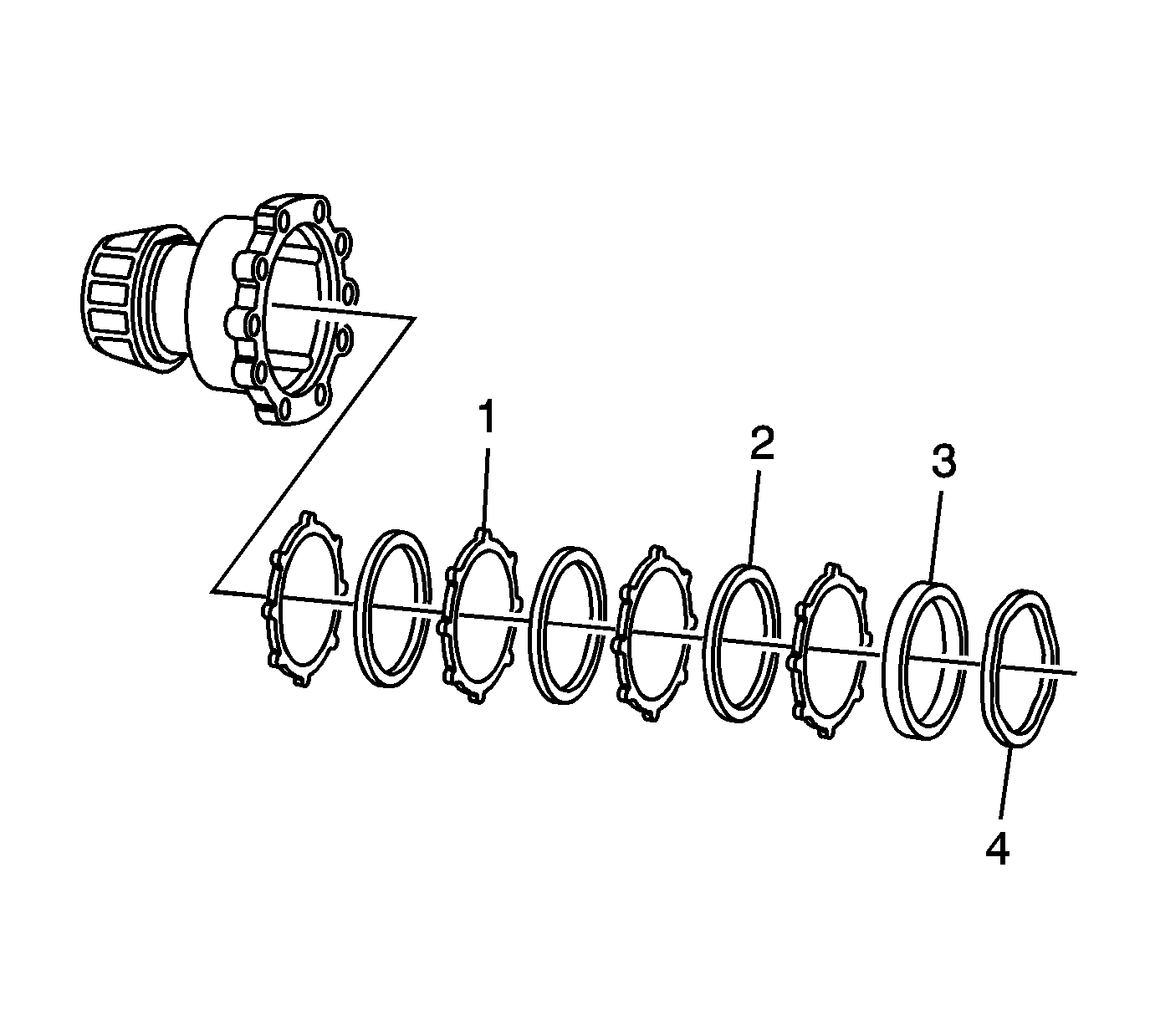
Important: Friction discs and separator plates develop specific wear patterns. During disc and plate installation, the components must be installed in the specific order in which they were removed.
- Install the left clutch pack to the left case.
| • | Install the separator plates (1). |
| • | Install the friction discs (2). |
| • | Install the friction disc (thick) (3). |
| • | Install the bellville washer (4). |
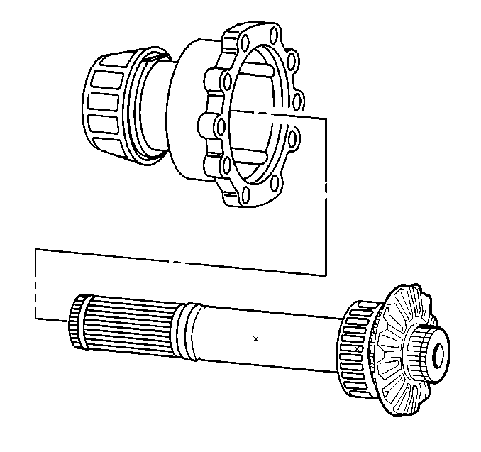
- Install the left intermediate shaft and gear to the left case.
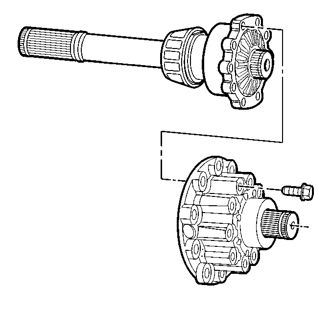
- Assemble the case halves.
Notice: Use the correct fastener in the correct location. Replacement fasteners
must be the correct part number for that application. Fasteners requiring
replacement or fasteners requiring the use of thread locking compound or sealant
are identified in the service procedure. Do not use paints, lubricants, or
corrosion inhibitors on fasteners or fastener joint surfaces unless specified.
These coatings affect fastener torque and joint clamping force and may damage
the fastener. Use the correct tightening sequence and specifications when
installing fasteners in order to avoid damage to parts and systems.
- Install the case bolts.
Tighten
Tighten the bolts to 55 N·m (41 lb ft).
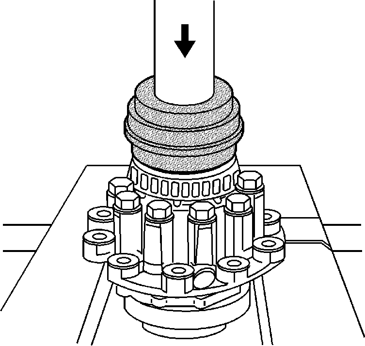
- Using the
J 42170
and a hydraulic press, install the
right side bearing to the differential.
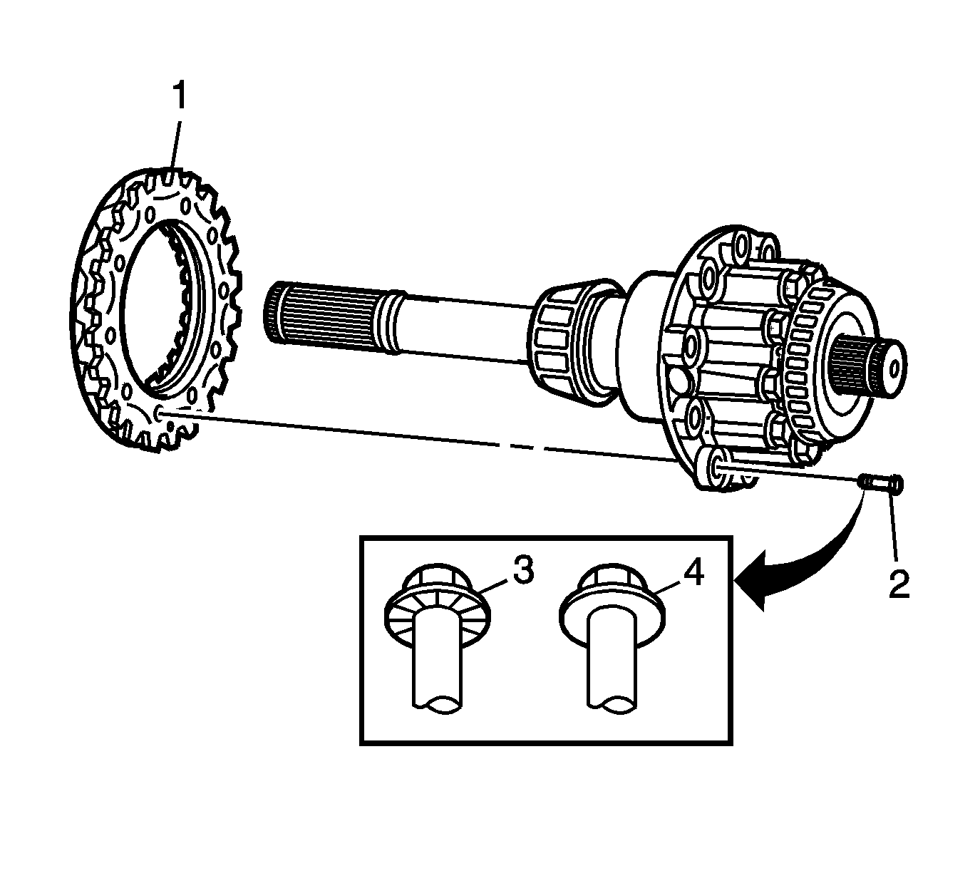
- Install the ring gear (1) to the differential. Use several bolts to properly align the ring gear to
the case.
A hammer and brass punch may be used to aid in seating the ring gear onto the differential case.
Important: Two types of ring gear bolts may be available for replacement. First design bolts (3) have serrations under the head and are torqued to 195 N·m (144 lb ft). The second design (4)
are smooth under the head and are torqued to 145 N·m (107 lb ft).
- Install the NEW ring gear bolts (2).
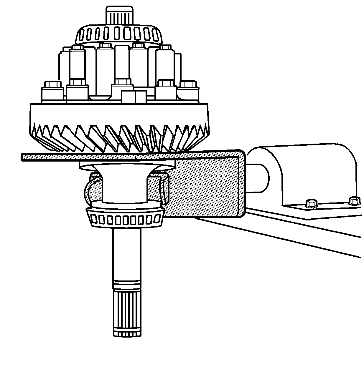
- Position the differential assembly onto the
J 42173
.
Tighten
Tighten the ring gear bolts to 195 N·m (144 lb ft) - 1st design.
Tighten
Tighten the ring gear bolts to 145 N·m (107 lb ft) - 2nd design.


