For 1990-2009 cars only
Removal Procedure
The electronically operated fuel filler door can be manually opened by pulling on the manual release cable. The location is in the rear compartment drivers side rear inner wheelhouse side trim.
- Remove the wheelhouse liner panel. Refer to Rear Wheelhouse Panel Liner Replacement .
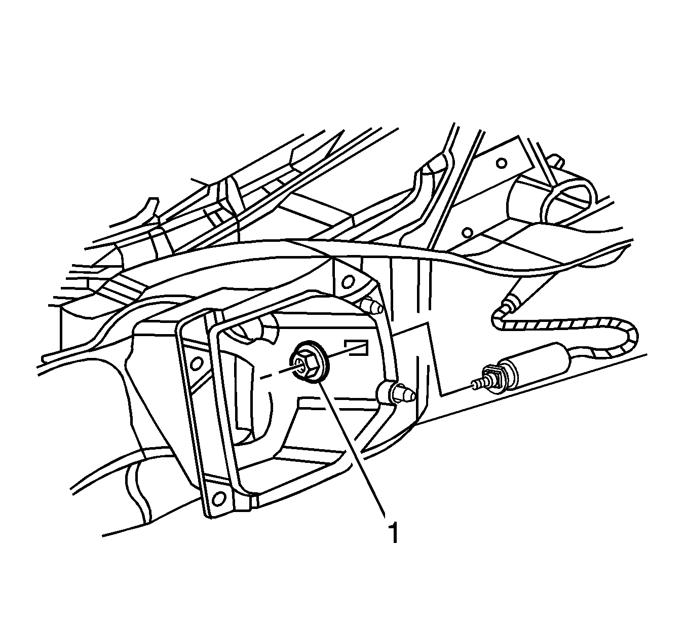
- Open the fuel door and remove the nut (1) attaching the fuel door release cable to the fuel pocket.
- Remove the driver side rear compartment trim. Refer to Rear Compartment Side Trim Replacement - Left Side
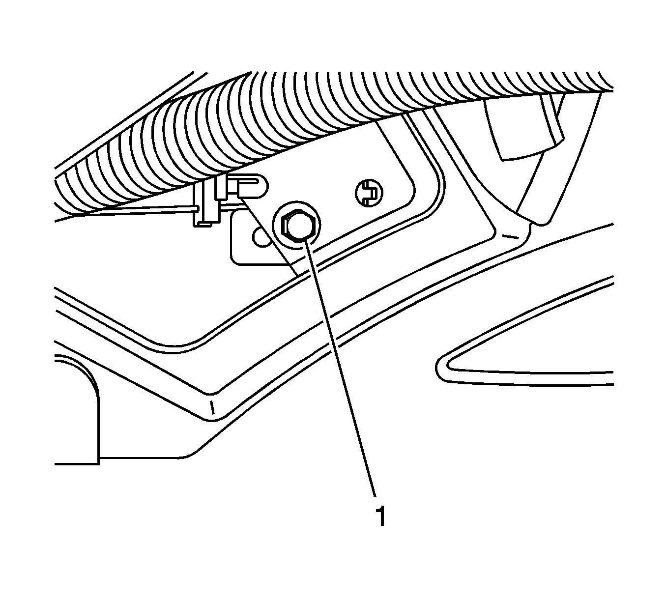
- Remove the bolt (1) securing the actuator.
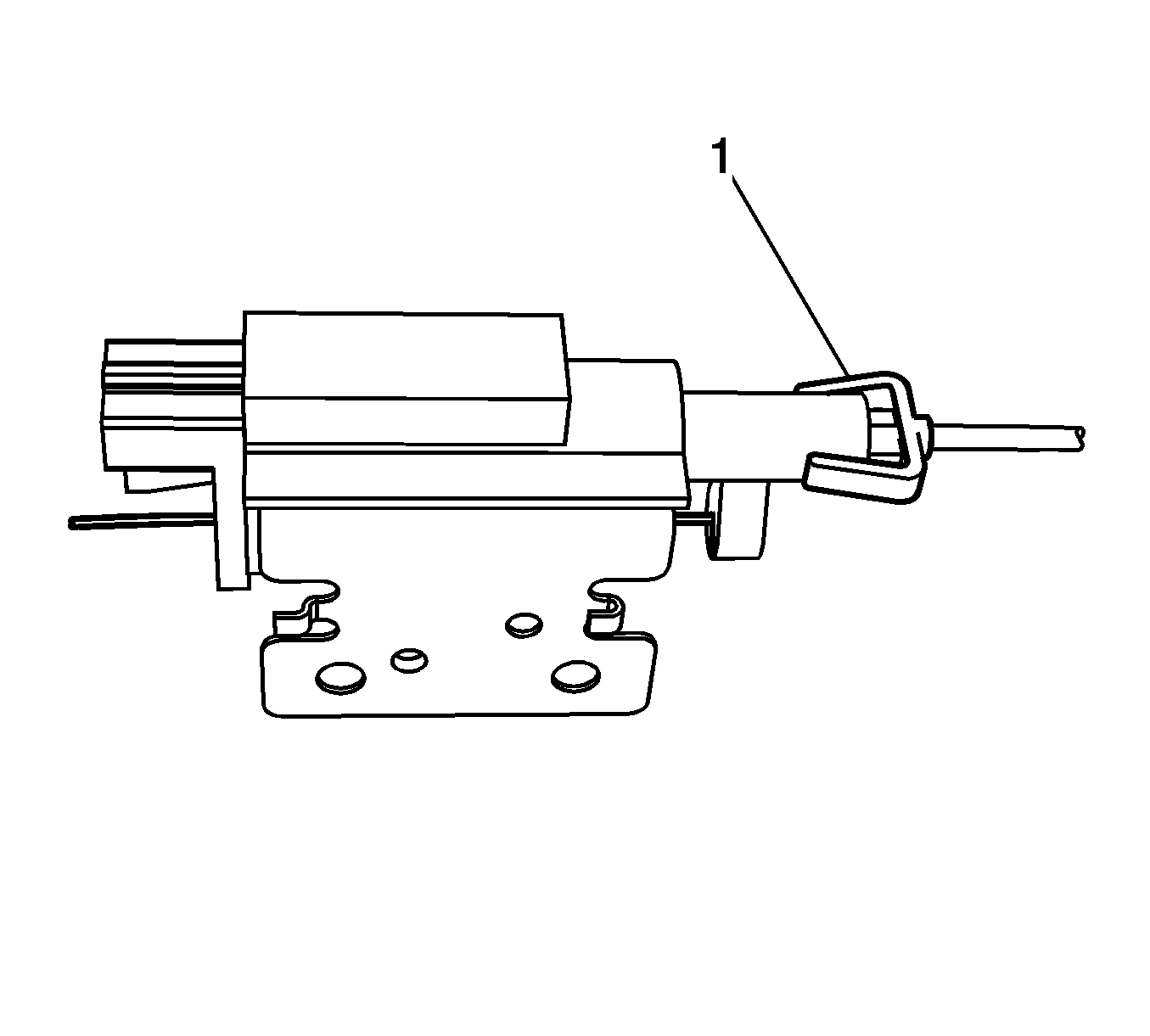
- Disconnect the fuel door release cable from the actuator (1).
- Remove the quarter panel. Refer to Rear Quarter Panel Replacement.
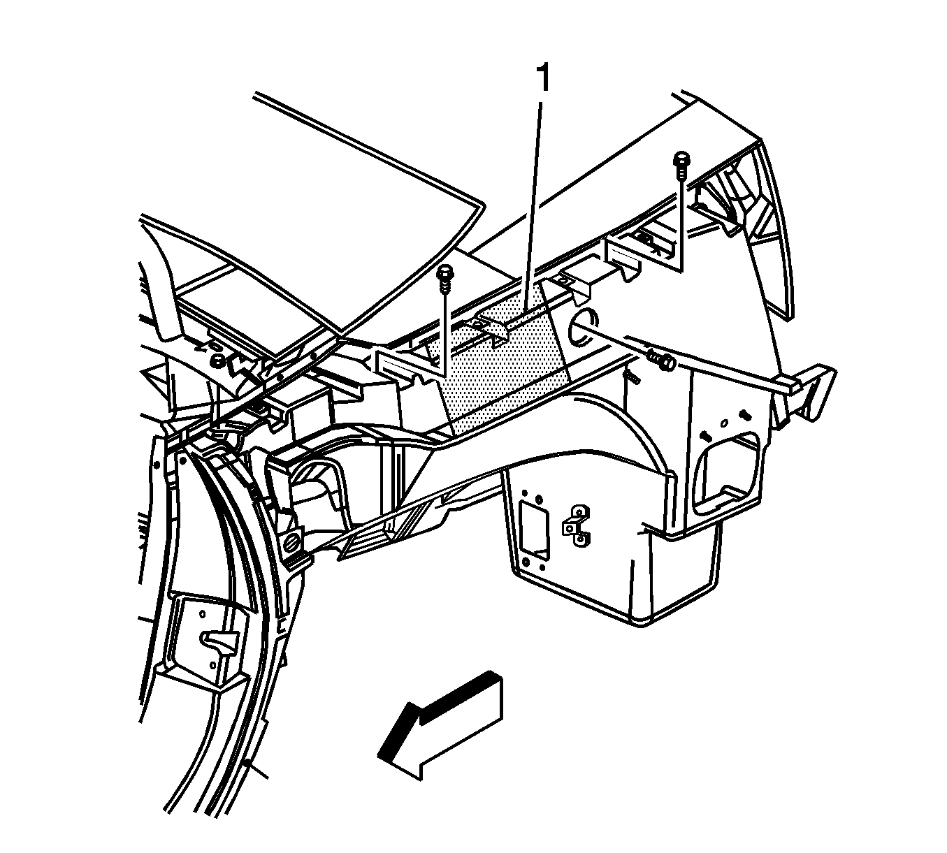
- Remove a section of the compartment panel frame (1) directly below where the fuel door release cable passes through the rear compartment panel.
- Save the cut-out section of the compartment panel frame.
- Remove the fuel door release cable.


Important: Due to accessibility of the fuel door release cable, a section of the compartment panel frame will have to be removed.
Installation Procedure
- Position the fuel door release cable.
- Connect the fuel door release cable to the actuator (1).
- Install the bolt (1) attaching the actuator.
- Install the cable to the fuel pocket.
- Install the nut (1) attaching the door release cable to the fuel filler pocket.
- Before applying the adhesive, dry fit the compartment panel frame section (1) for proper fit and alignment.
- Clean and prepare all bonding mating surfaces according to the adhesive manufactures recommendations. Refer to Sheet Molded Compound (SMC) Panel Bonding.
- Create 50 mm (2 in) wide backing plates to be installed along the back side of the section joint.
- Apply a consistent bead of structural adhesive to the backing plate strips and clamp or mechanically fasten along the section joint. Refer to Sheet Molded Compound (SMC) Panel Bonding.
- Remove any excess adhesive.
- Apply a consistent bead of structural adhesive to the compartment panel frame section. Refer to Sheet Molded Compound (SMC) Panel Bonding.
- Position the compartment panel frame section.
- Apply pressure to the compartment panel frame section to set the adhesive.
- Clamp or mechanically fasten the compartment panel frame section into place.
- Remove any excess adhesive.
- Install the driver side rear compartment trim. Refer to Rear Compartment Side Trim Replacement - Left Side
- Install the wheelhouse liner panel. Refer to Rear Wheelhouse Panel Liner Replacement .
- Install the quarter panel. Refer to Rear Quarter Panel Replacement.

Notice: Refer to Fastener Notice in the Preface section.

Tighten
Tighten the nut to 2 N·m (18 lb in).

Tighten
Tighten the nut to 2 N·m (18 lb in).

