For 1990-2009 cars only
Removal Procedure
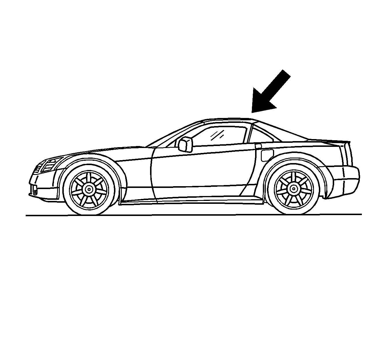
- Place the folding top in the up position.
- Open the rear compartment.
- Disconnect the battery. Refer to Battery Negative Cable Disconnection and Connection in Engine Electrical.
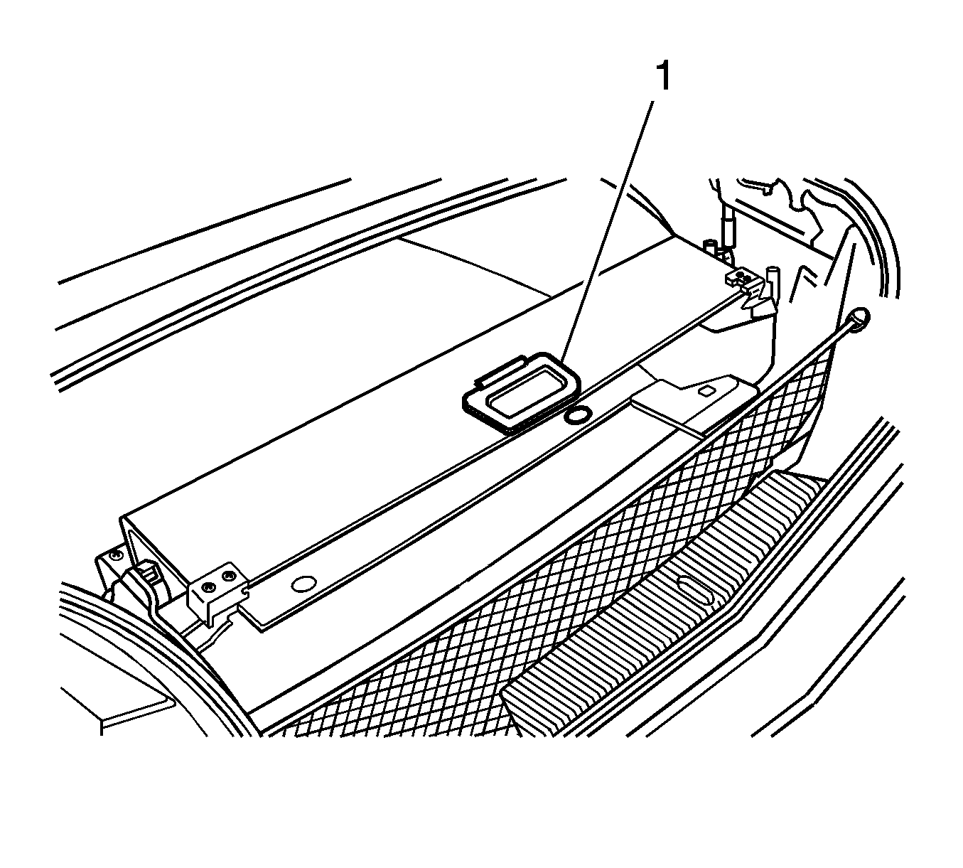
- Lower the rear compartment partition (1).
- Place a protective covering over the rear compartment interior and the adjacent body panels.
- Remove the side compartment trim. Refer to Rear Compartment Side Trim Replacement - Left Side or to Rear Compartment Side Trim Replacement - Right Side in Body Rear End.
- Locate the hydraulic pump beneath the carpet in the storage compartment on the driver side of the rear compartment.
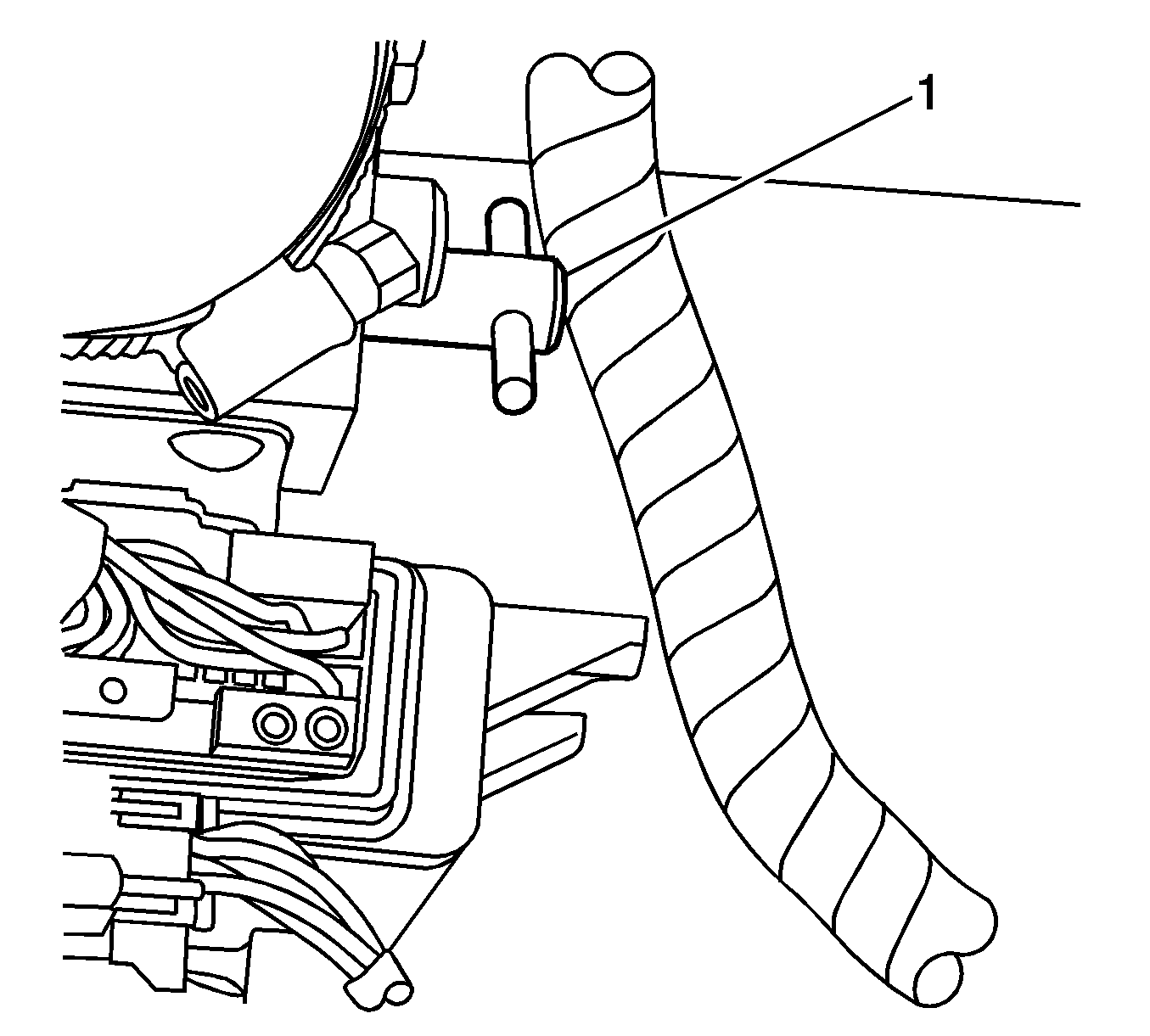
- Turn the hydraulic pump bypass valve (1) counterclockwise until the valve stops.
- When replacing the left side, perform the following steps. Skip these steps for the right side:
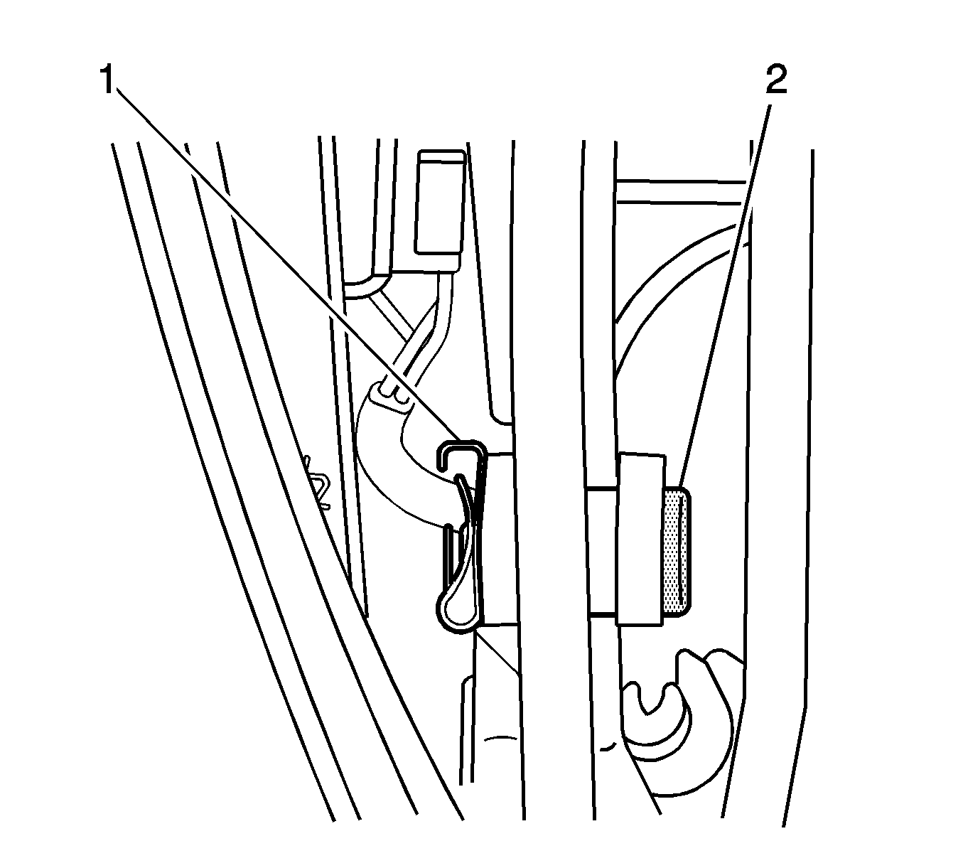
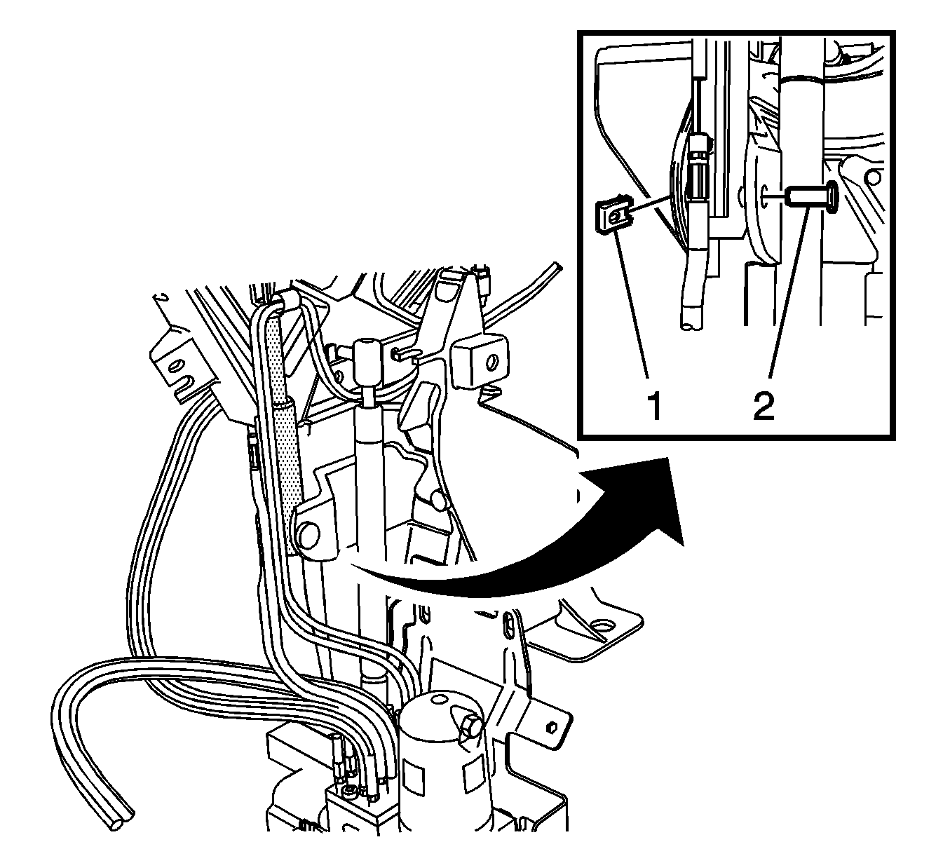
- Remove the spring-clip (1) from the upper compartment lid hydraulic cylinder retainer pin.
- Remove the upper cylinder retainer pin (2).
- Remove the spring-clip (1) from the lower compartment lid hydraulic cylinder retainer.
- Remove the lower cylinder retainer pin (2).
- Leaving the hydraulic hoses attached, remove the cylinder from the original position. Set the cylinder aside in a safe place.
- Remove the compartment lid strut actuator. Refer to Folding Top Compartment Lid Strut Actuator Replacement - Rear .
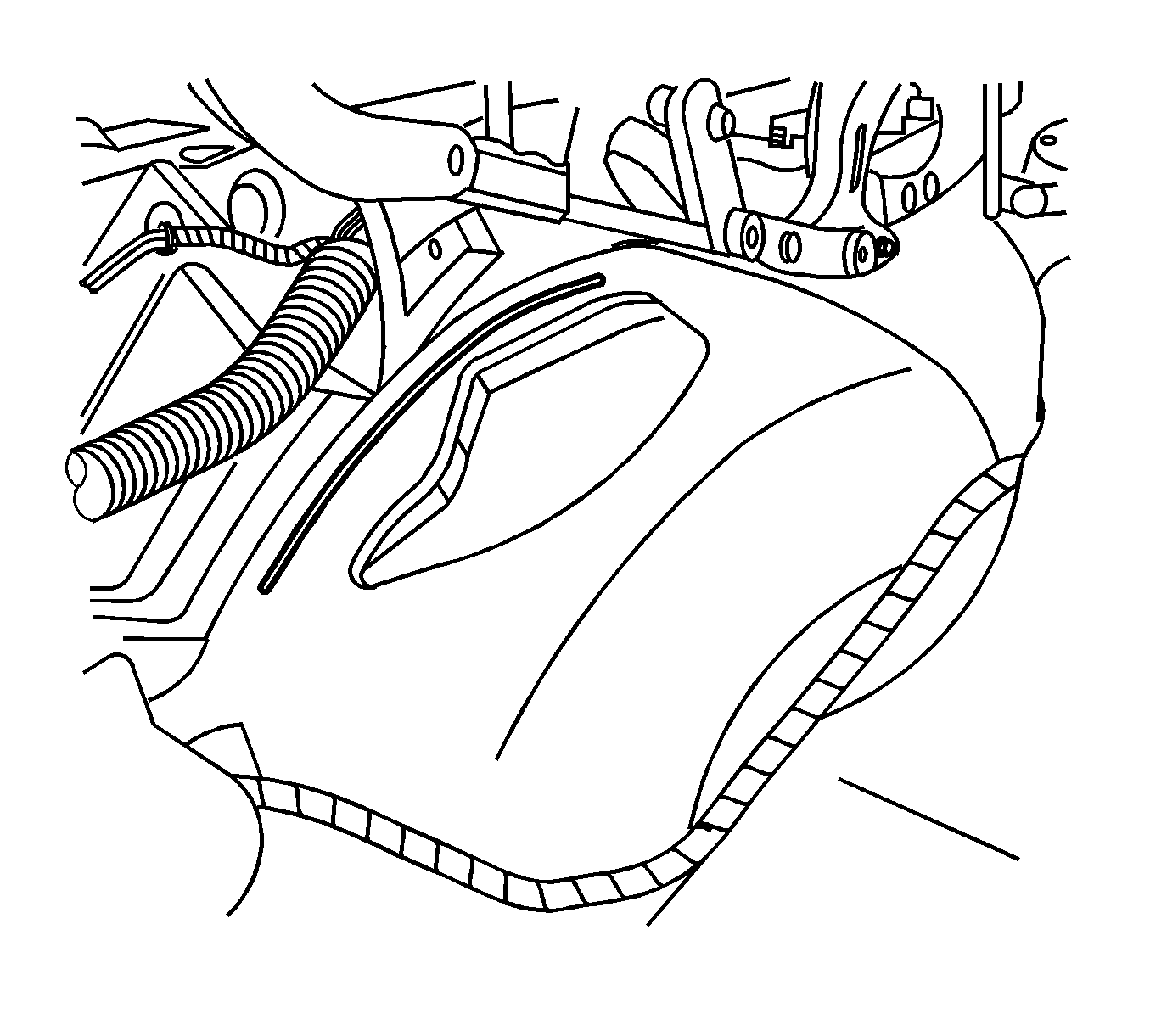
- Using a light colored grease pencil, mark the sound deadener mat on the wheelhouse along the inboard edge of the quarter inner longitudinal support frame. This mark will be used to verify that the frame has not shifted when the support is removed.
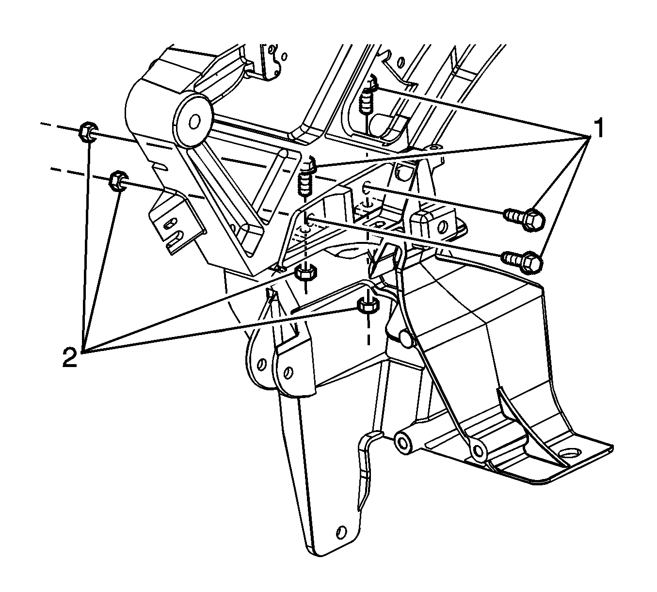
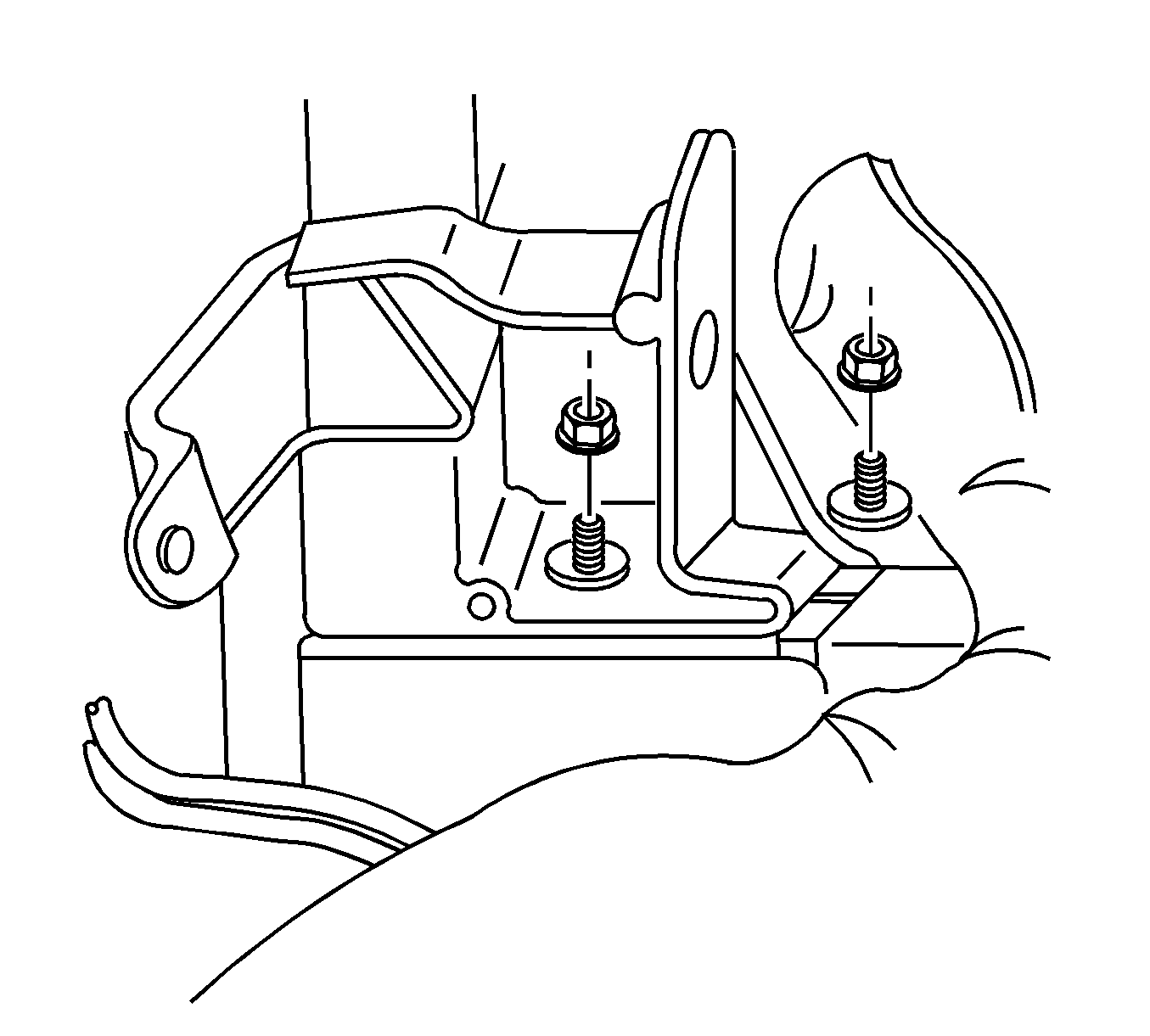
- Remove the bolts (1) and nuts (2) securing the quarter inner frame support bracket to the longitudinal support frame.
- Place the shims (1), as required, between the bottom surface of the longitudinal support frame and the wheelhouse mat. The shims should support the frame at the current elevation, but not lift the frame off the wheelhouse.
- Pull the carpet up and over the retaining stud. Peel back enough carpet to access the area.
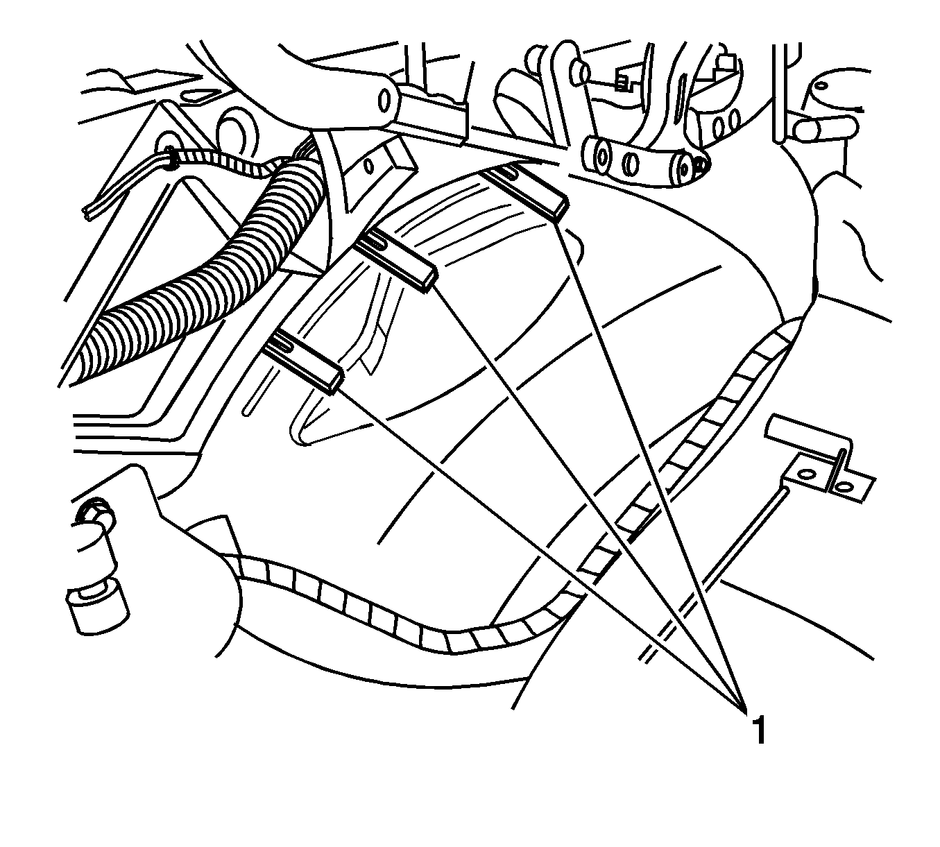
- Remove the nuts that secure the quarter inner frame support bracket to the weld studs coming up through the floor.
- Remove the wheelhouse liner panel in order to access the 2nd weld stud head for drilling. Refer to Rear Wheelhouse Panel Liner Replacement .
- From the underside of the vehicle, drill out the center of the weld studs enough to break the heads loose from the floor.
- Remove the remaining studs.
- Lower the vehicle.
- Remove the quarter inner frame support bracket by sliding the bracket free toward the center of the vehicle.
Caution: Refer to Eye Protection Caution in the Preface section.
Caution: Refer to Folding Top Hydraulic Pressure Caution in the Preface section.
Caution: Refer to Servicing Electrical Components Caution in the Preface section.
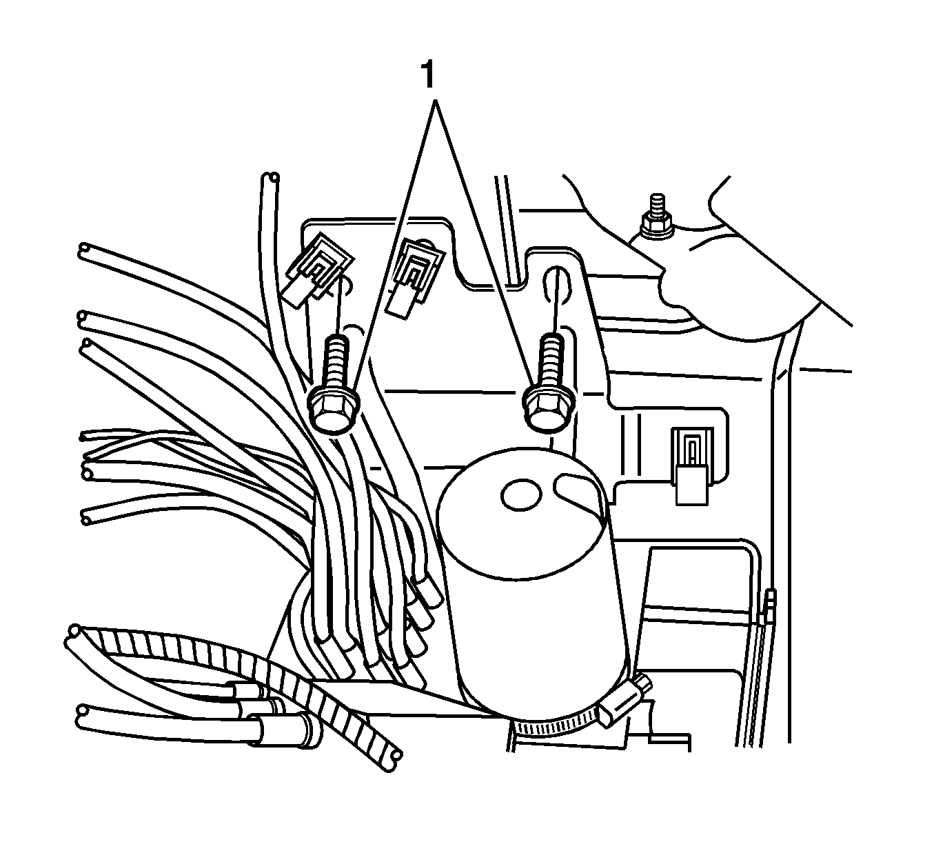
| 9.1. | Remove the bolts (1) from the hydraulic pump bracket. |
| 9.2. | Set the pump on the storage compartment floor. |
Important: Mark the location of any shims found between the quarter inner frame support bracket and the longitudinal support frame and/or floor.
Installation Procedure
- Install any previously removed floor shims to the marked area(s).
- Position the quarter inner frame support bracket to the vehicle by sliding the bracket from center outward.
- Install any previously removed shims into position between the frame support bracket and the longitudinal support frame.
- Ensure that the longitudinal support frame is still aligned to the grease pencil mark on the sound deadener. Install the bolts attaching the frame support bracket to the longitudinal support frame.
- From the underside of the vehicle, insert an M8 flange head bolt or Hex with flat washer through the bracket where the studs were previously drilled out.
- From the rear compartment, install the original nut/washer onto the 2 bolts.
- When replacing the left side, perform the following steps. Skip these steps for the right side:
- Install the compartment lid strut actuator. Refer to Folding Top Compartment Lid Strut Actuator Replacement - Rear .
- Install the compartment lid hydraulic cylinder to the link.
- Install the lower cylinder retainer pin (2).
- Install the lower cylinder retainer spring-clip (1).
- Install the upper cylinder retainer pin (2).
- Install the spring-clip to the upper cylinder retainer pin.
- Remove the positioning shims between the longitudinal support frame and the wheelhouse mat.
- Install the side compartment trim. Refer to Rear Compartment Side Trim Replacement - Left Side or to Rear Compartment Side Trim Replacement - Right Side in Body Rear End.
- Remove the protective covering from the rear compartment.
- Turn the pump bypass valve (1) clockwise until the valve stops.
- Raise the rear compartment partition (1).
- Connect the battery. Refer to Battery Negative Cable Disconnection and Connection in Engine Electrical.
- Inspect the hydraulic system for fluid leaks.
- Inspect the hydraulic system fluid level and add fluid as needed. Refer to Folding Top Fluid Addition .
- Close the rear compartment.
- Inspect the folding top for proper operation. Refer to Power Folding Top Description and Operation .
- Raise the vehicle.
- Rustproof the bolt heads and the surrounding metal on the undercarriage.
- Install the wheelhouse liner panel. Refer to Rear Wheelhouse Panel Liner Replacement .
Notice: Refer to Fastener Notice in the Preface section.

Important: Reverse the bolt on the vertical surface of the frame support bracket so the nut is on the inside. This will allow access with a torque wrench.
Tighten
Tighten the bolts to 37 N·m (27 lb ft)
Tighten
Tighten the nuts to 37 N·m (27 lb ft)

| 7.1. | Position the hydraulic pump to the mounting location. |
| 7.2. | Apply Loctite® Blue, GM P/N 12345382 (Canadian P/N 10953489) or equivalent to the bolts. |
| 7.3. | Install the bolts (1) to the hydraulic pump bracket. |
Tighten
Tighten the bolts to 18 N·m (13 lb ft).


