For 1990-2009 cars only
Removal Procedure
- Remove the LH closeout trim panel. Refer to Instrument Panel Insulator Panel Replacement - Left Side in Instrument Panel, Gages, and Console.
- Remove the instrument panel cluster (IPC). Refer to Instrument Cluster Replacement in Instrument Panel, Gages, and Console.
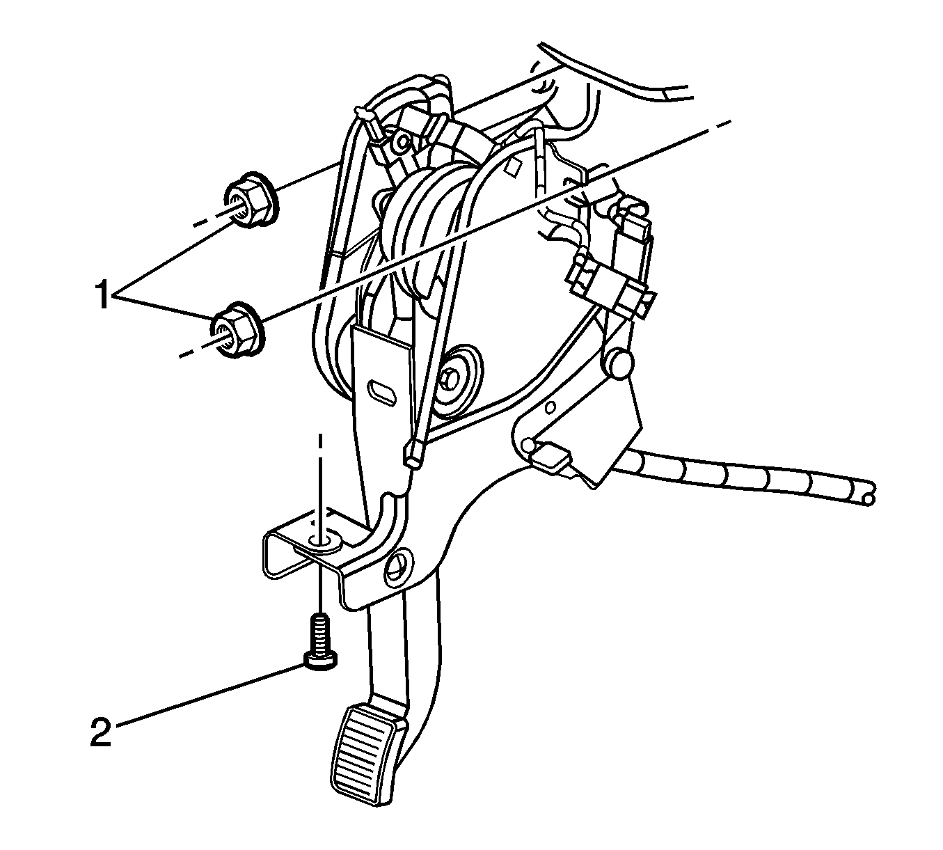
- Remove the park brake assembly attaching nuts (1) and bolt (2).
- Disconnect the park brake switch electrical connector.
- Disconnect the park brake release solenoid electrical connector.
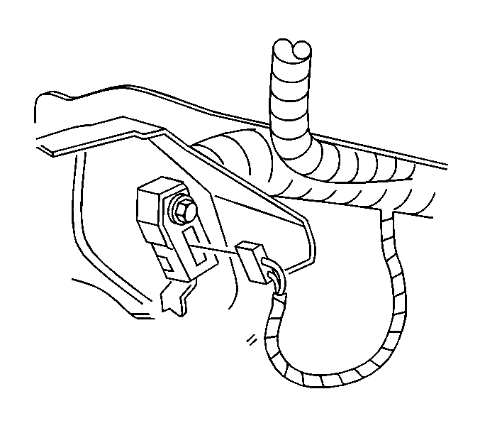
- Position the park brake pedal assembly aside to gain access to the park brake warning lamp switch.
- Remove the park brake warning lamp switch retainer.
- Remove the park brake warning lamp switch from the park brake pedal assembly.


Installation Procedure
- Install the park brake warning lamp switch to the park brake assembly.
- Install the park brake warning lamp switch retainer.
- Position the park brake pedal assembly.
- Install the park brake pedal assembly retaining nuts and bolt.
- Connect the park brake release solenoid electrical connector.
- Connect the park brake switch electrical connector.
- Install the IPC. Refer to Instrument Cluster Replacement in Instrument Panel, Gages, and Console.
- Install the LH closeout trim panel. Refer to Instrument Panel Insulator Panel Replacement - Left Side in Instrument Panel, Gages, and Console.
- Apply the park brake pedal and release 2-3 times, to assure proper function of the park brake system.
Notice: Refer to Fastener Notice in the Preface section.
Tighten
Tighten to 4 N·m (35 lb in).
Tighten
Tighten to 10 N·m (89 lb in).

