For 1990-2009 cars only
Tie Rod Replacement Outer
Tools Required
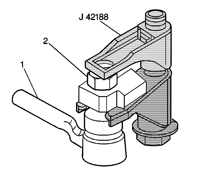
J 42188 Ball Joint Separator
Removal Procedure
- Raise and support the vehicle. Refer to Lifting and Jacking the Vehicle .
- Remove the tire and wheel assembly. Refer to Tire and Wheel Removal and Installation .
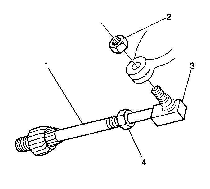
- Loosen, do not remove, the outer tie rod end stud nut (2) from the outer tie rod end ball stud.
- Install J 42188 between the steering knuckle and the outer tie rod end stud.
- Tighten the bolt on J 42188 until the steering knuckle and the outer tie rod end stud separate.
- Remove J 42188 and the outer tie rod end stud nut.
- Remove the outer tie rod end stud from the suspension knuckle.
- Loosen the jam nut (4) on the rear suspension adjustment link.
- Remove the outer tie rod end (3) from the rear suspension adjustment link (1).


Installation Procedure
- Install the outer tie rod end (3) to the rear suspension adjustment link (1).
- Install the outer tie rod end into the suspension knuckle.
- Install the outer tie rod end nut (2).
- Install the tire and wheel assembly. Refer to Tire and Wheel Removal and Installation .
- Lower the vehicle.
- Adjust the rear wheel toe as necessary and tighten the rear suspension adjustment link lock nut. Refer to Rear Toe Adjustment .

Notice: Refer to Fastener Notice in the Preface section.
Tighten
| • | Tighten the outer tie rod end nut (2) to 20 N·m (15 lb ft) to seat the outer tie rod stud. |
| • | Turn the nut an additional 160 degrees. |
| • | Check the outer tie rod end nut for a minimum torque of 60 N·m (45 lb ft). |
Tie Rod Replacement Inner
Removal Procedure
- Raise and support the vehicle. Refer to Lifting and Jacking the Vehicle .
- Remove the tire and wheel assembly. Refer to Tire and Wheel Removal and Installation .
- Disconnect the outer tie rod end from the suspension knuckle. Refer to Tie Rod Replacement .
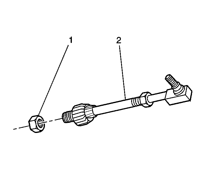
- Remove the nut (1) retaining the rear suspension adjustment link to the crossmember.
- Remove the rear suspension adjustment link (2) from the vehicle.

Installation Procedure
- Install the rear suspension adjustment link (2) to the vehicle.
- Install the rear suspension adjustment link nut (1) to the back side of the crossmember.
- Install the outer tie rod end into the suspension knuckle. Refer to Tie Rod Replacement .
- Install the tire and wheel assembly. Refer to Tire and Wheel Removal and Installation .
- Lower the vehicle.
- Adjust the rear wheel toe as necessary. Refer to Rear Toe Adjustment .

Notice: Refer to Fastener Notice in the Preface section.
Tighten
Tighten the rear suspension adjustment link nut to 60 N·m (44 lb ft).
