Tools Required
J39765-A Fuel Sender Lock Ring Tool
Removal Procedure

- Disconnect the negative battery cable. Refer to
Battery Negative Cable Disconnection and Connection .
- Remove the left fuel tank. Refer to
Fuel Tank Replacement - Left Side .
- Place the fuel tank on a suitable work surface.
- Disconnect the fuel pump electrical jumper harness from the fuel pump module.
- Disconnect the fuel feed line from the retainer on the side of the fuel tank.

Important: The fuel pump module is spring loaded and will spring upward when the locking ring is removed.
- Using the
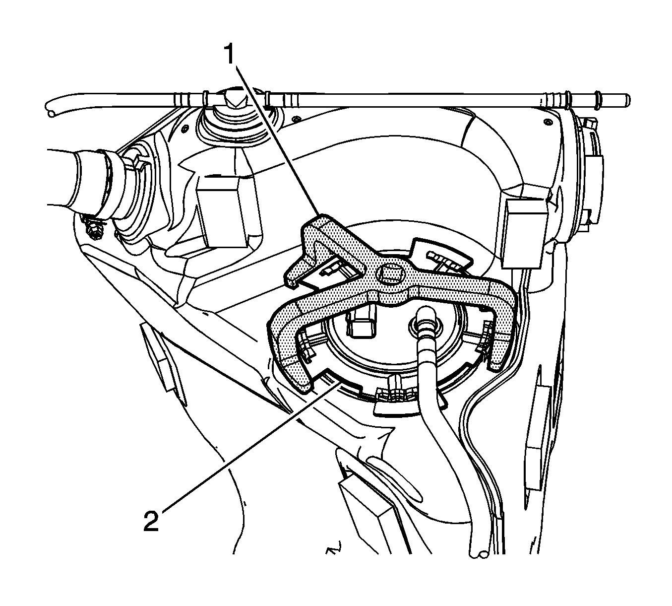
J39765-A (1), remove the fuel pump module locking ring (2), by turning the
J39765-A in a counterclockwise direction.

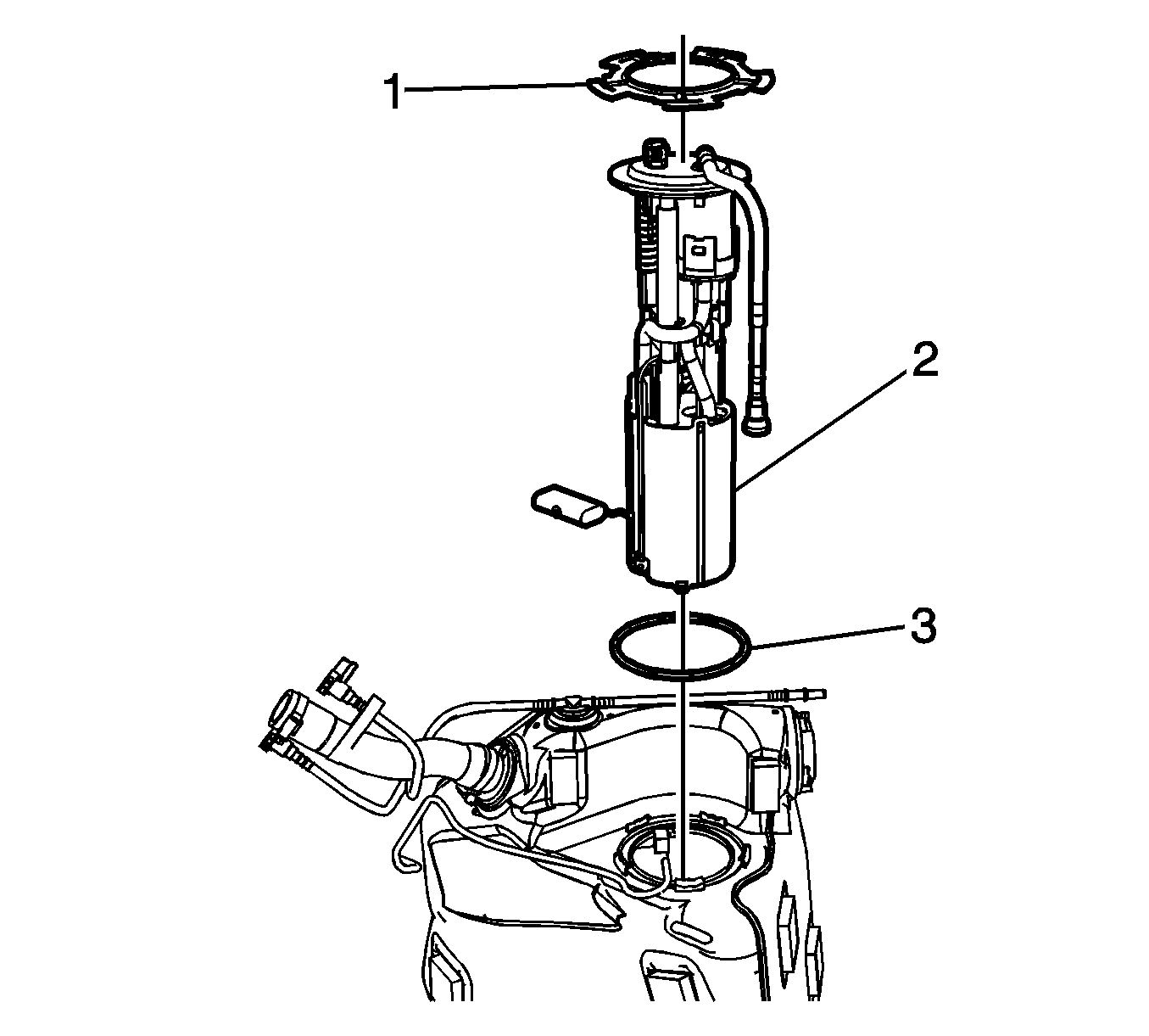
- Carefully remove the fuel pump module (2) half way from the fuel tank, with the internal fuel lines connected. Use care to prevent damage to the fuel sender float arm.
- Disconnect the jet line quick-connect fitting from the fuel pump module inner port.
- Remove the jet line from the module cup and retainer. This line has no connector.
- Remove the fuel pump module O-ring (3) from the fuel tank opening.
Installation Procedure

- Install a new fuel pump module O-ring (3) to the fuel tank opening.
- Place mechanics wire around the internal fuel lines in the fuel tank. This will permit line access once the pump module is inserted into the fuel tank.
- Install the pump module (2) into the fuel tank half way , using care not to damage the float arm.
- Using the mechanics wire, gently pull the fuel lines up through the fuel pump module opening.
- Place the fuel line with no connector through the retainer and into the module cup.
Important: Pull on the connector to ensure that the connector is secure.
- Connect the fuel line quick-connect fitting to the fuel pump module inner port.
- Remove the mechanics wire from the internal fuel lines.
- Install the fuel pump module lock ring (1) into position on the fuel tank module.
- Align the fuel tank module to the installed position.
- Compress the fuel pump module into the fuel tank.

- Using the
J39765-A (1), fully lock the fuel pump module lock ring (2) in place, by turning the
J39765-A in a clockwise direction.
- Connect the fuel supply line into the clip on the side of the fuel tank.
- Using a digital multi-meter, verify the full and empty readings resistance reading of the fuel pump module. Turn the fuel tank upside down to achieve the full tank reading.
Resistance
| • | Empty tank reading 250 Ω resistance |
| • | Full tank reading 40 Ω resistance |

- Connect the fuel pump jumper harness to the fuel pump module.
- Install the left fuel tank. Refer to
Fuel Tank Replacement - Left Side .
- Connect the negative battery cable. Refer to
Battery Negative Cable Disconnection and Connection .
- Perform the following procedure in order to test for leaks:
| 17.1. | Turn ON the ignition switch, for 2 seconds. |
| 17.2. | Turn OFF the ignition, for 10 seconds. |
| 17.3. | Turn ON the ignition. |
| 17.4. | Inspect for fuel leaks. |
Specification
| • | Pump on: 400 kPa (58 psi) |
| • | Pump off: 359 kPa (52 psi) |
- Program the transmitters. Refer to
Transmitter Programming .


