For 1990-2009 cars only
Tools Required
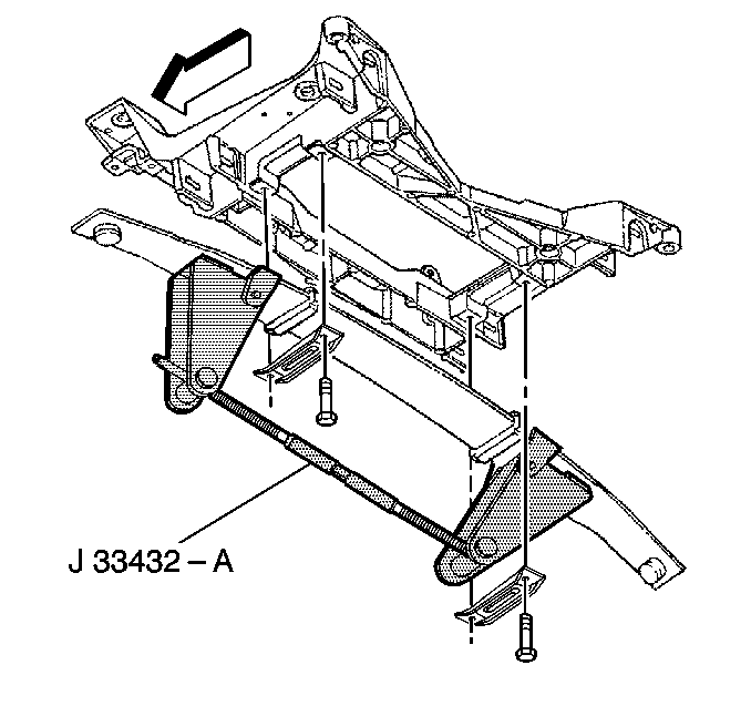
J 33432-A Leaf Spring Compressor
Removal Procedure
- Support the engine. Refer to Engine Support Fixture .
- Raise and support the vehicle. Refer to Lifting and Jacking the Vehicle .
- Remove the tire and wheel assemblies. Refer to Tire and Wheel Removal and Installation .
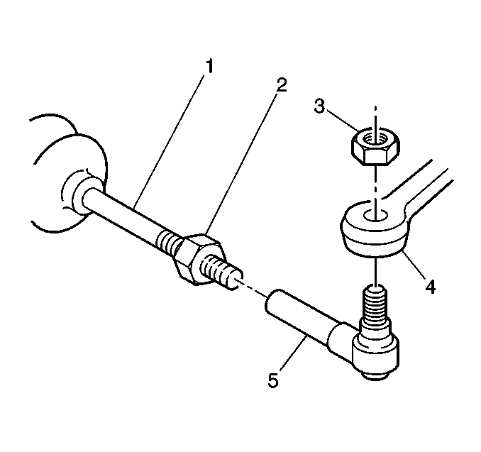
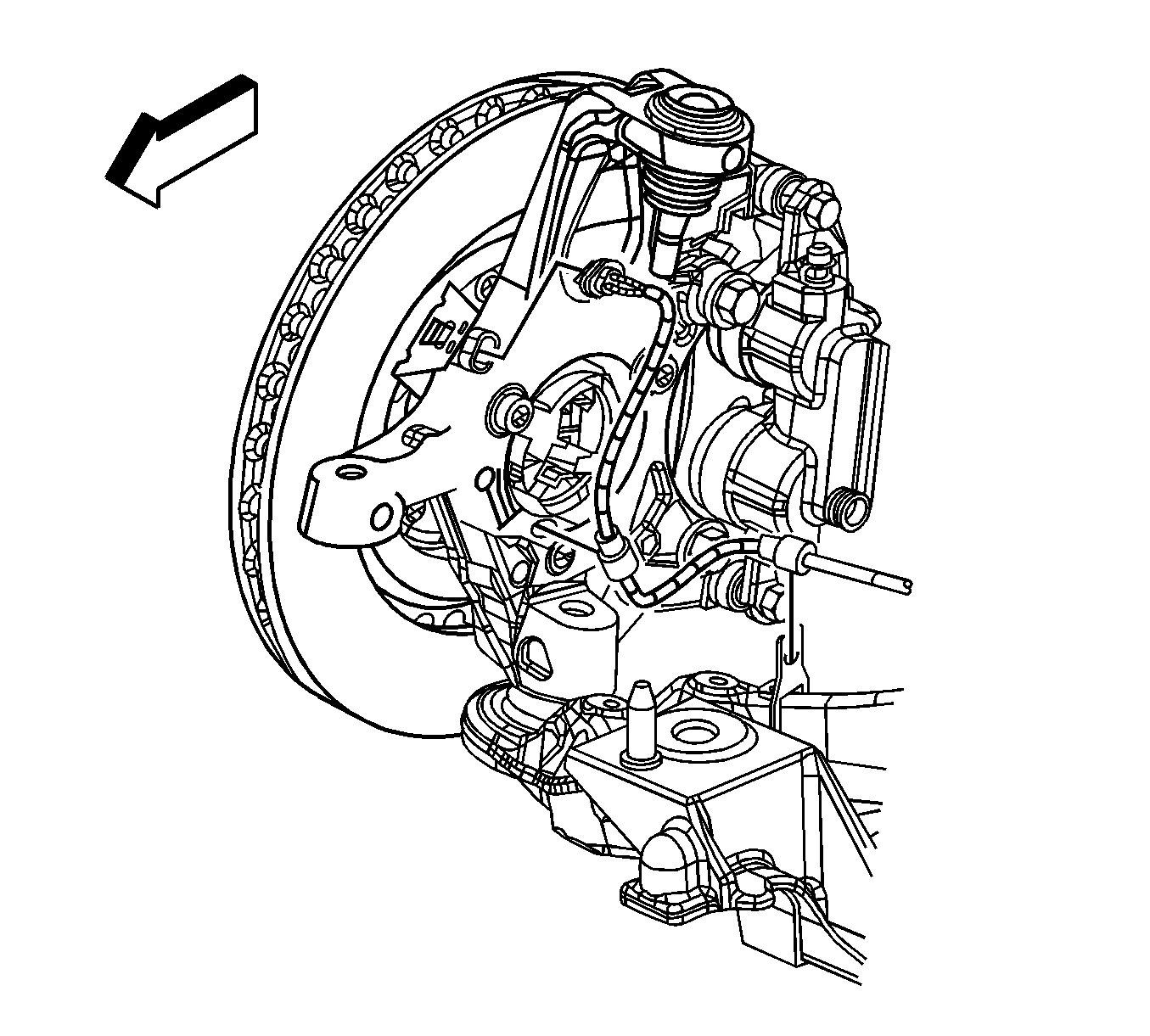
- Remove the steering linkage outer tie rod end stud nuts (3). Refer to Rack and Pinion Outer Tie Rod End Replacement .
- Disconnect the electronic suspension control (ESC) sensor links. Refer to Electronic Suspension Front Position Sensor Replacement .
- Remove the stabilizer shaft from the vehicle. Refer to Stabilizer Shaft Replacement .
- Disconnect the intermediate shaft lower coupling from the steering gear. Refer to Intermediate Steering Shaft Replacement .
- Remove the bolts from the electronic brake control module (EBCM)/brake pressure modulator valve (BPMV) bracket. Refer to Brake Pressure Modulator Valve Bracket Replacement .
- Support and reposition the EBCM/BPMV and bracket away from the crossmember.
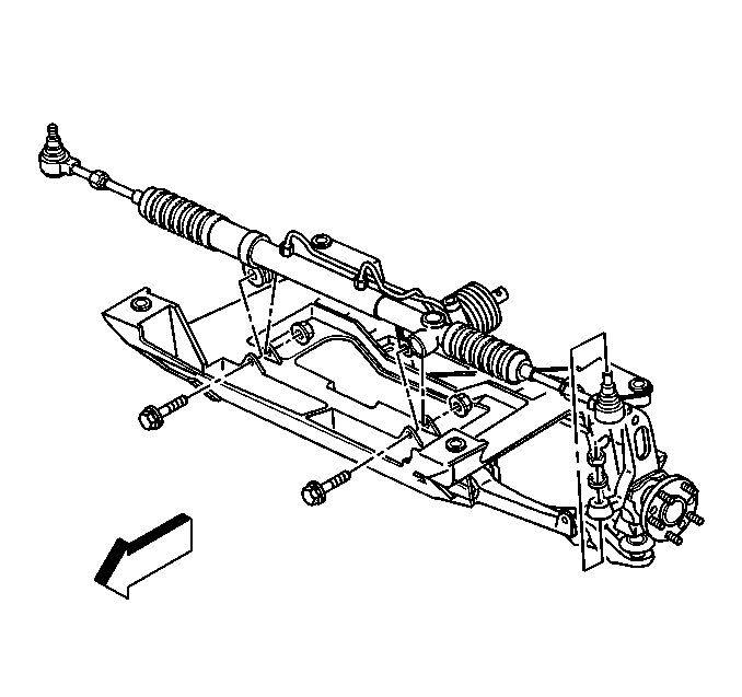
- Remove the power steering gear mounting bolts.
- Remove the power steering fluid cooler from the crossmember.
- Lift the power steering gear off of the crossmember and support.
- Using the J 33432-A , remove the transverse spring from the vehicle. Refer to Front Transverse Spring Replacement .
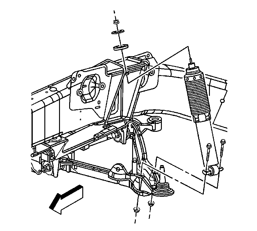
- Disconnect the lower shock absorber bolts from the lower control arms.
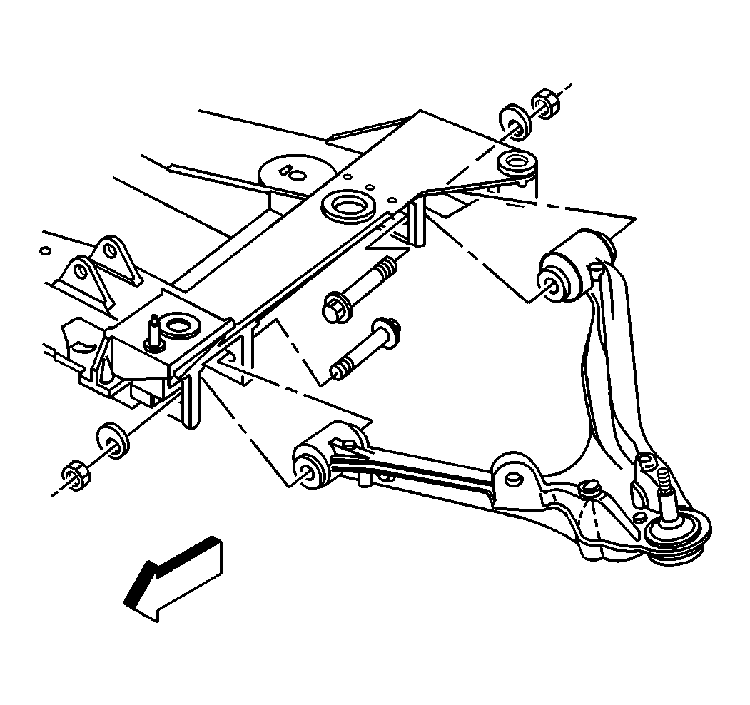
- Remove the lower control arm bolts from the crossmember.
- Place a transmission jack under the crossmember.
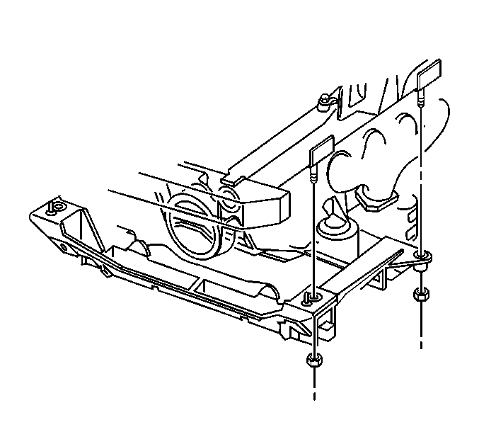
- Remove the engine mount lower nuts. Refer to the following procedures:
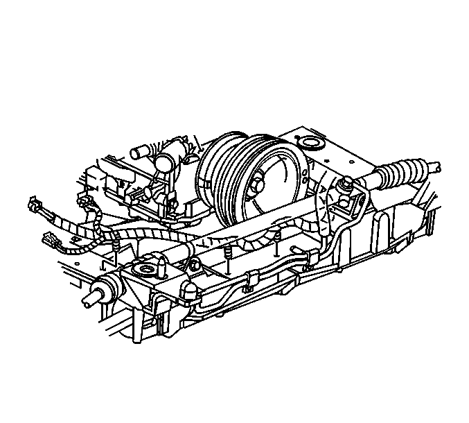
- Disconnect the wheel speed sensor wiring harness from the crossmember.
- Disconnect the electrical harness from the clips on the crossmember.
- Disconnect the brake pipe from the clips on the crossmember.
- Remove the crossmember mounting nuts.
- Lower the crossmember out of the vehicle by removing the transmission jack from under the crossmember.
Installation Procedure
- Raise the crossmember to the vehicle.
- Install new crossmember mounting nuts.
- Install the engine mount lower nuts. Refer to one of the following procedures:
- Fasten the wheel speed sensor wiring harness retaining clips to the crossmember.
- Fasten the brake pipe to the retaining clips on the crossmember.
- Connect the electrical harness to the clips on the crossmember.
- Connect the brake pipe to the clips on the crossmember.
- Install the transverse spring with the J 33432-A connected, to the crossmember. Refer to Front Transverse Spring Replacement .
- Install the lower control arm to the crossmember. Refer to Lower Control Arm Replacement .
- Install the shock absorbers to the lower control arms.
- Install the power steering gear to the crossmember.
- Install the bolts to the BPMV bracket. Refer to Brake Pressure Modulator Valve Bracket Replacement .
- Connect the intermediate shaft to the steering gear. Refer to Intermediate Steering Shaft Replacement .
- Install the steering linkage outer tie rod ends to the steering knuckles. Refer to Rack and Pinion Outer Tie Rod End Replacement .
- Connect the electronic suspension control (ESC) sensor links. Refer to Electronic Suspension Front Position Sensor Replacement .
- Install the stabilizer shaft to the vehicle. Refer to Stabilizer Shaft Replacement .
- Install the tire and wheel assemblies. Refer to Tire and Wheel Removal and Installation .
- Lower the vehicle.
- Remove engine support fixture from the engine. Refer to Engine Support Fixture .
- Perform a vehicle front end alignment. Refer to Wheel Alignment Measurement .

| 1.1. | Align the crossmember dowel pins to the frame rails. |
| 1.2. | Align the engine mount studs. |
Notice: Refer to Fastener Notice in the Preface section.
Tighten
Tighten the new crossmember mounting nuts to 110 N·m (81 lb ft).


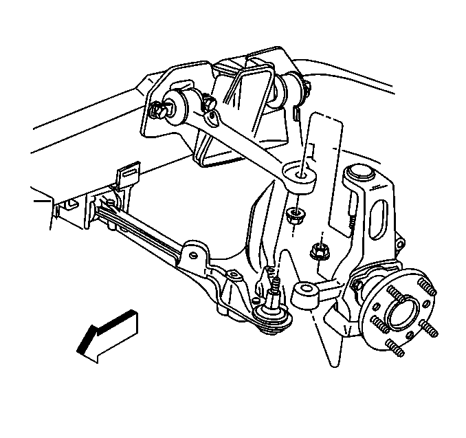

Tighten
Tighten the shock absorber lower mounting nuts to 28 N·m (21 lb ft).

Tighten
Tighten the power steering gear mounting bolts to 100 N·m (74 lb ft).
