For 1990-2009 cars only
Removal Procedure
- Disable the SIR system. Refer to SIR Disabling and Enabling.
- Remove the steering column bracket. Refer to Steering Column Bracket Replacement .
- Remove the steering column trim covers. Refer to Steering Column Trim Covers Replacement.
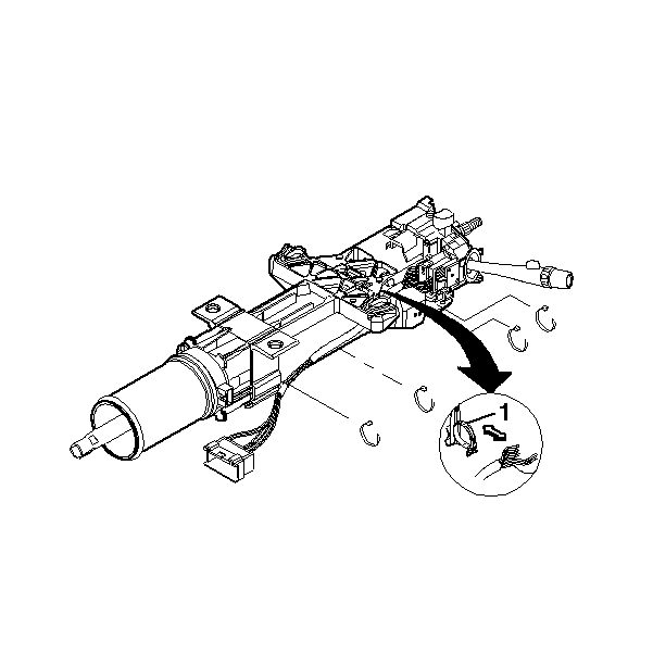
- Remove the wire harness assembly from the wire restraint clips (1).
- Disconnect the wire connector.
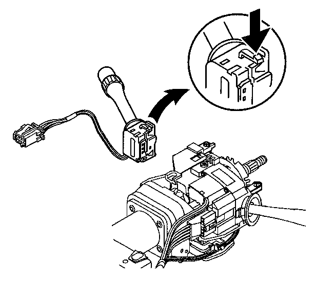
- Disconnect the windshield wiper and washer switch assembly.
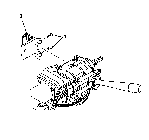
- Remove the switch assembly in the following manner.
- Remove the 2 pan head tapping screws (1).
- Remove the switch mounting bracket (2).
- Remove the turn signal cancel cam and steering shaft upper bearing spring. Refer to Turn Signal Cancel Cam and Steering Shaft Upper Bearing Spring Replacement .
- Remove the turn signal and multifunction switch assembly only. Refer to Turn Signal Multifunction Switch Replacement .
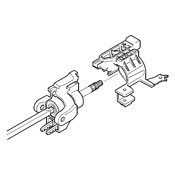
- Slide the switch mounting bracket off of the steering column shaft assembly.
Caution: Refer to SIR Caution in the Preface section.


| 7.1. | Press on the locking tabs of the switch assembly. |
| 7.2. | Pull the switch assembly out of the switch mounting bracket. |

Important: To remove the side mounted bracket perform the following steps.
If not a side mounted bracket go to step 10.
Important: To remove the slide on mounting bracket perform the following steps.
Installation Procedure
- Install the side mounted switch mounting bracket (2) to the steering column tilt head assembly.
- Install the 2 pan head tapping screws (1).
- To install the windshield washer and wiper switch assembly go to step 7.
- Slide the switch mounting bracket onto the steering column shaft assembly.
- Install the turn signal and multifunction switch assembly only. Refer to Turn Signal Multifunction Switch Replacement .
- Install the turn signal cancel cam and steering shaft upper bearing spring. Refer to Turn Signal Cancel Cam and Steering Shaft Upper Bearing Spring Replacement .
- If necessary, install the switch assembly into the switch mounting bracket so that the locking tabs snap into place.
- Connect the wire harness assembly.
- Install new wire harness straps.
- Install the wire harness assembly into the wire restraint clips (1).
- Install the steering column trim covers. Refer to Steering Column Trim Covers Replacement.
- Install the steering column bracket. Refer to Steering Column Bracket Replacement.
- Enable the SIR system. Refer to SIR Disabling and Enabling.

If not a side mounted bracket go to step 3.
Notice: Refer to Fastener Notice in the Preface section.
Tighten
Tighten the screws to 7 N·m (62 lb in).

Important: The switch mounting bracket must be pressed firmly against the steering column tilt head in order for the screws from the turn signal and multifunction switch assembly screws to line up.


