Tools Required
J 42055 Transmission Support Fixture
Removal Procedure
Notice: Failure to follow the proper removal and installation procedures may result in damage to the engine crankshaft thrust bearing.
Notice: When tilting down the rear of the driveline, observe the clearance between the rear of the engine and the composite dash panel. Do not allow the engine to rest unsupported against the composite dash panel, or vehicle damage may result.
Notice: When lowering and removing the rear of the driveline, observe the clearance between the rear of the transaxle assembly and the underbody to prevent damage.
- Raise and support the vehicle. Refer to Lifting and Jacking the Vehicle .
- Remove the differential to transmission lower nut.
- Remove the driveline support assembly. Refer to Driveline Support Assembly Replacement .
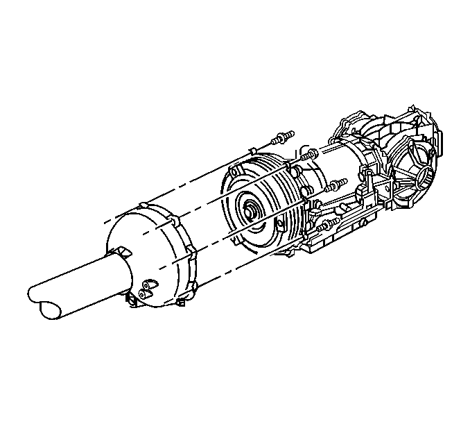
- Remove the transmission to driveline support assembly bolts/studs.
- Insert a flat-bladed screwdriver, or similar tool, between the edge of the driveline support assembly and the transmission, then begin to pry the driveline support assembly loose from the transmission.
- Slowly slide the driveline support assembly away from the transmission while supporting the transmission torque converter.
- Using a strap positioned from side-to-side, secure the transmission torque converter to the transmission.
- Remove the differential to transmission bolts and nuts.
- SLOWLY slide the differential from the transmission.
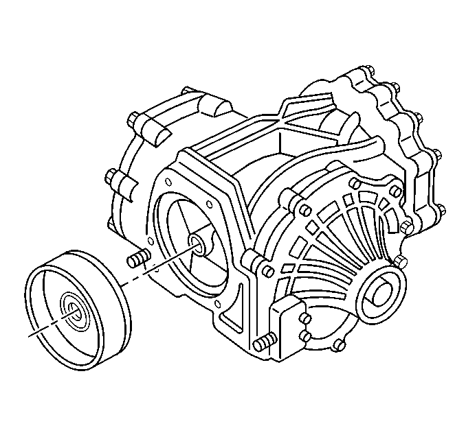
- Remove the differential plate from the differential.
- Remove the transmission from the J 42055 , if necessary.
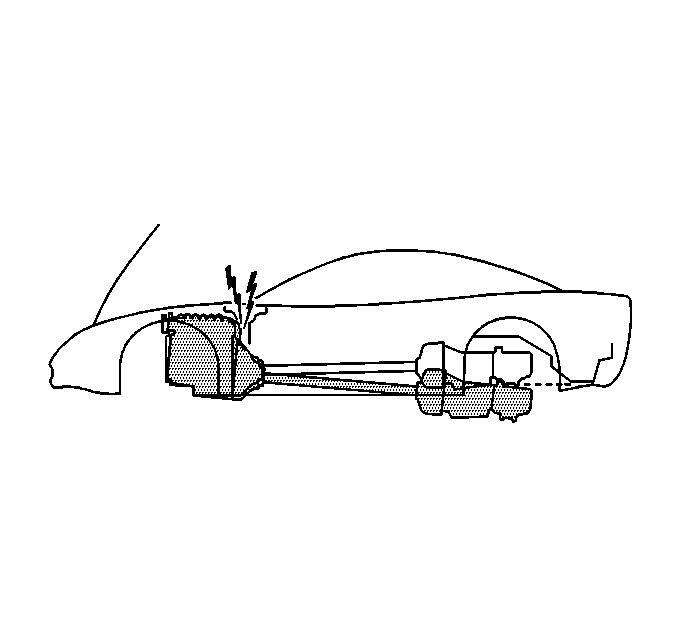
Removing the nut at this time will aid in separating the differential from the transmission after the driveline has been removed from the vehicle.
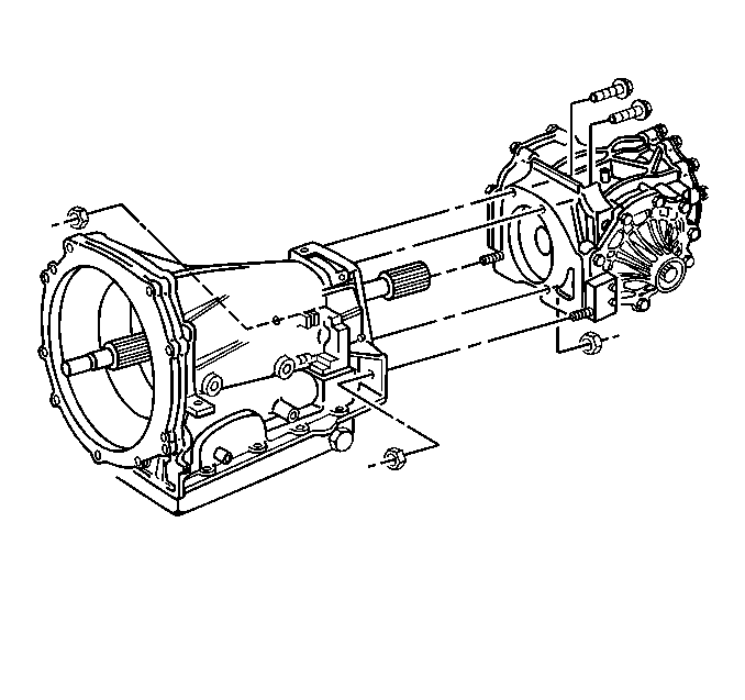
Important: Use care when separating the differential from the transmission to not damage the transmission output shaft seal in the differential plate.
Installation Procedure
Notice: Failure to follow the proper removal and installation procedures may result in damage to the engine crankshaft thrust bearing.
- Install the transmission to the J 42055 , if removed.
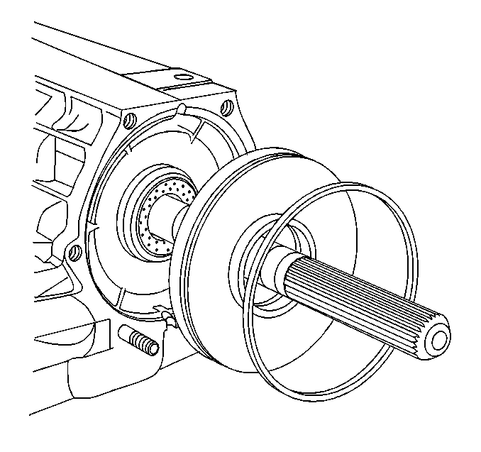
- Install the differential plate to the transmission, use care not to damage the transmission output seal in the rear of the plate.
- Position the differential plate seal flush with the transmission case.
- SLOWLY slide the differential to the transmission.
- Install the differential to transmission bolts and nuts.
- Install the driveline support assembly. Refer to Driveline Support Assembly Replacement .
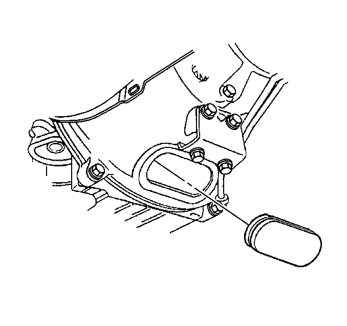
- Install the engine flywheel housing access plug.
- Flush the transmission oil cooler. Refer to Transmission Fluid Cooler Flushing and Flow Test .
- Lower the vehicle.
- Check the transmission fluid level. Refer to Transmission Fluid Check .
- Program the transmission control module. Refer to Control Module References .
- Road test the vehicle.
- Inspect for fluid leaks.
- Perform a final inspection for the proper fluid level.

Notice: Refer to Fastener Notice in the Preface section.
Tighten
Tighten the differential to transmission bolts and nuts to 50 N·m (37 lb ft).
Important: After an internal transmission repair or internal part replacement, the Transmission Control Module Programming and Setup procedure should be performed.
