For 1990-2009 cars only
Tools Required
J 42058 Frame Adapter Clamp
Removal Procedure
- Disable the SIR system. Refer to SIR Disabling and Enabling .
- Disconnect the negative battery cable. Refer to Battery Negative Cable Disconnection and Connection .
- Remove all related panels and components.
- Remove the front impact bar. Refer to Front Bumper Impact Bar Replacement .
- Note the location and remove the sealers and anti-corrosion materials from the repair area, as necessary. Refer to Anti-Corrosion Treatment and Repair .
- Restore as much of the damage as possible to the factory specifications. Refer to Dimensions - Body .
- Use J 42058 to secure the vehicle if pulling and straightening is required.
- Inspect the front of dash panel, floor panels, and all other sheet molded compound (SMC) for cracks or areas that may need to be repaired or resealed. Refer to Rigid Plastic Part Repair Materials .
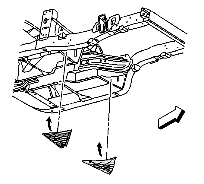
- Remove any welds as necessary and pry up the extension panel to expose the frame rail.
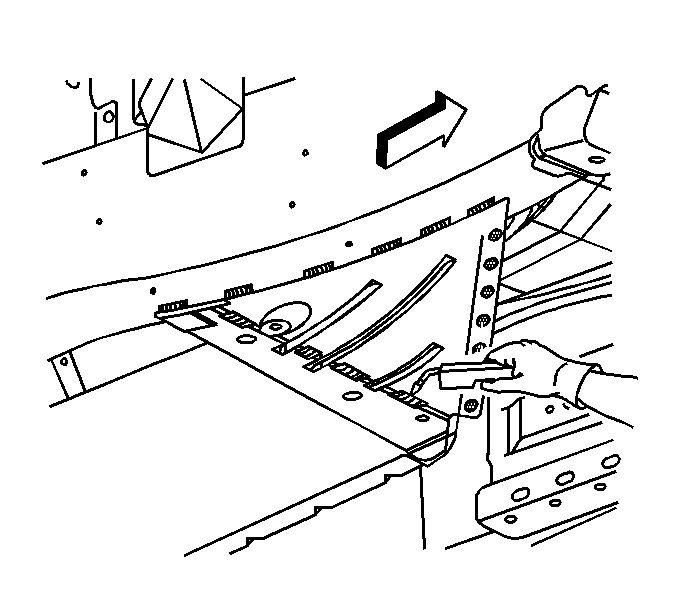
- Apply 50 mm (2 in) tape to the lower floor extension panel where the SMC front floor panel stops and the lower floor extension panel begins.
- Using a die grinder, cut along the forward edge of the tape to create a 50 mm (2 in) flange.
- Locate and drill out all factory welds. Note the number and location of the welds for installation of the new lower floor extension panel.
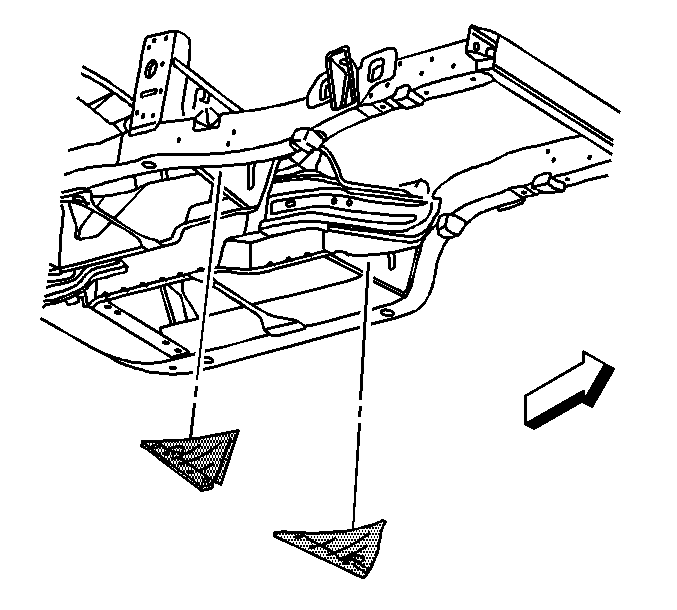
- Remove the lower floor extension panel.
- Using a die grinder cut through the stitch welds that attach the tunnel brace to the frame rail. Make cuts favoring the frame rail side of the welds.
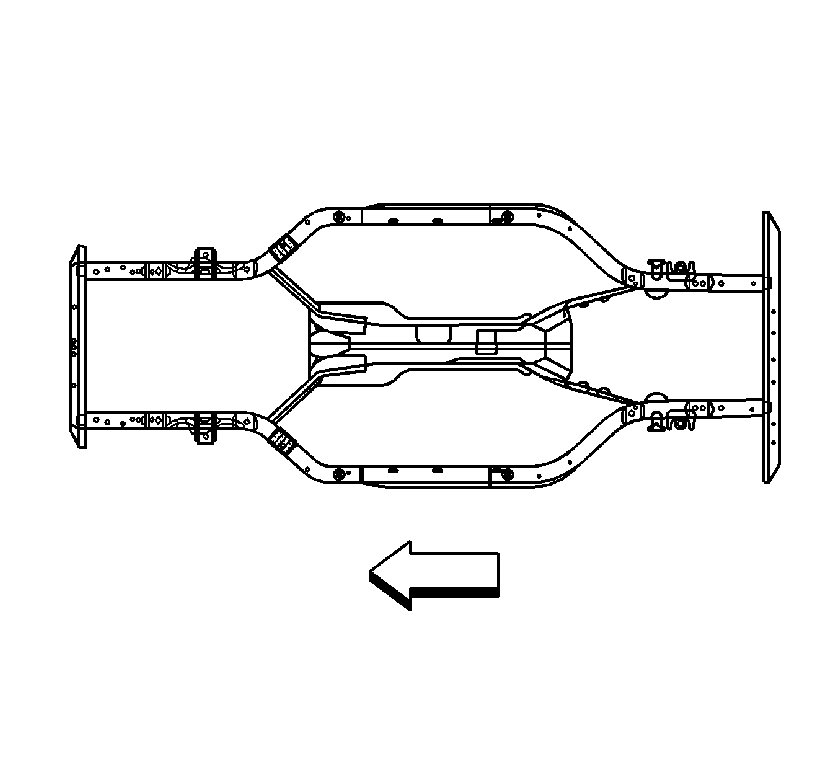
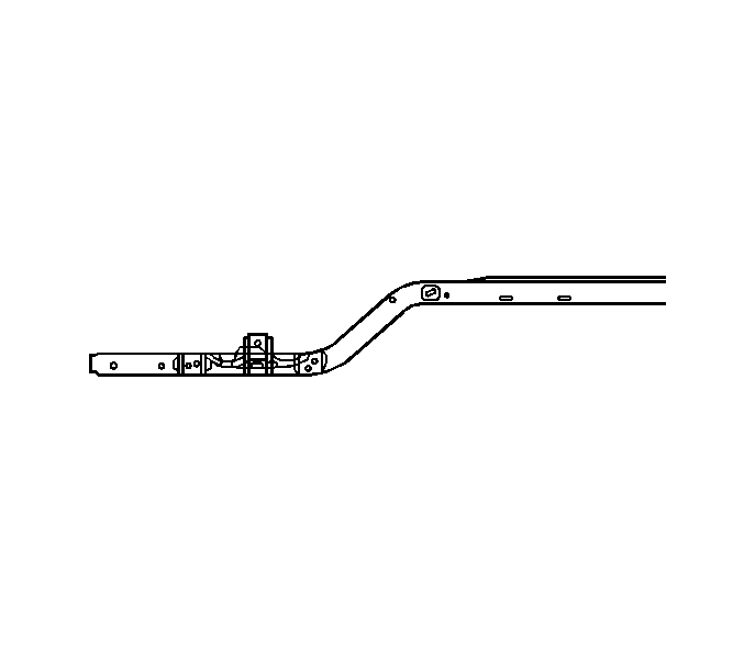
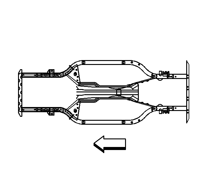
- Remove the damaged section of the frame rail within the shaded area.
Caution: Refer to Approved Equipment for Collision Repair Caution in the Preface section.
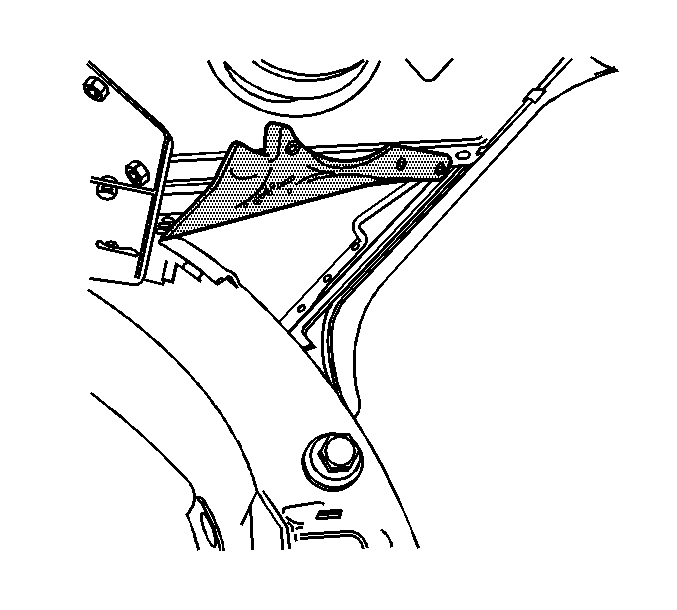
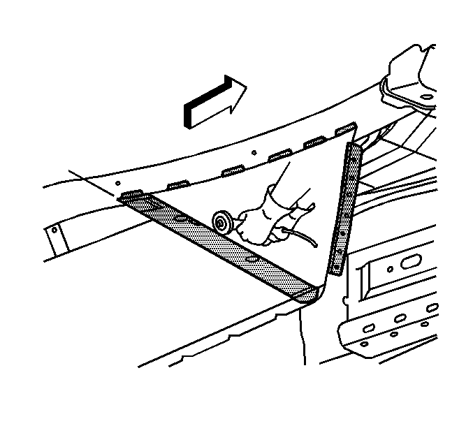
Important: The new lower floor extension panel is to be reinstalled 50 mm (2 in) forward of the SMC front floor panel. This will eliminate the potential to de-bond the front floor panel when reinstalling the lower floor extension panel.
Installation Procedure
- Determine the sectioning joint location within the recommended area.
- Cut the new frame section from the new frame rail assembly.
- Perform the offset lap joint sectioning. Refer to Offset Lap Joint Repair .
- Clean and prepare all of the welded mating surfaces.
- Apply 3M weld-thru coating P/N 05916 or equivalent as necessary.
- Using a Metal Inert Gas (MIG) welder, stitch weld the tunnel brace to the frame rail duplicating the factory welds.
- Drill 8 mm (5/16 in) holes in the new lower floor extension panel for plug welding.
- Replace the lower floor extension panel. Trim to fit and tuck the lower floor extension panel inside of the 50 mm (2 in) flange created from the original extension.
- Using a MIG welder, tack weld the lower floor extension panel in to place.
- Using a MIG welder, weld a 25 mm (1 in) stitch along the flange created from the original extension.
- Using a MIG welder, stitch weld the lower floor extension panel to the frame rail duplicating the factory welds.
- Using a MIG welder, plug weld the lower floor extension panel to the tunnel brace.
- Re-position the extension panel.
- Using a MIG welder, weld the extension panel duplicating the factory welds.
- Install the front impact bar. Refer to Front Bumper Impact Bar Replacement .
- Apply the sealers and anti-corrosion materials to the repair area, as necessary. Refer to Anti-Corrosion Treatment and Repair .
- Paint the repair area. Refer to Basecoat/Clearcoat Paint Systems .
- Install all related panels and components.
- Connect the negative battery cable. Refer to Battery Negative Cable Disconnection and Connection .
- Enable the SIR system. Refer to SIR Disabling and Enabling .
Caution: Refer to Collision Sectioning Caution in the Preface section.
