For 1990-2009 cars only
Special Tools
| • | EN 46109 Guide Pins |
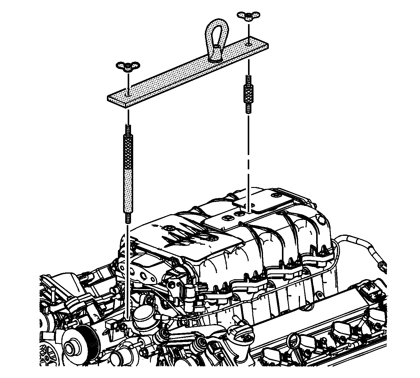
| • | EN-47748 Supercharger Lifting Fixture |
| • | EN-47833 Supercharger Service Holding Fixture |
For equivalent regional tools, refer to Special Tools
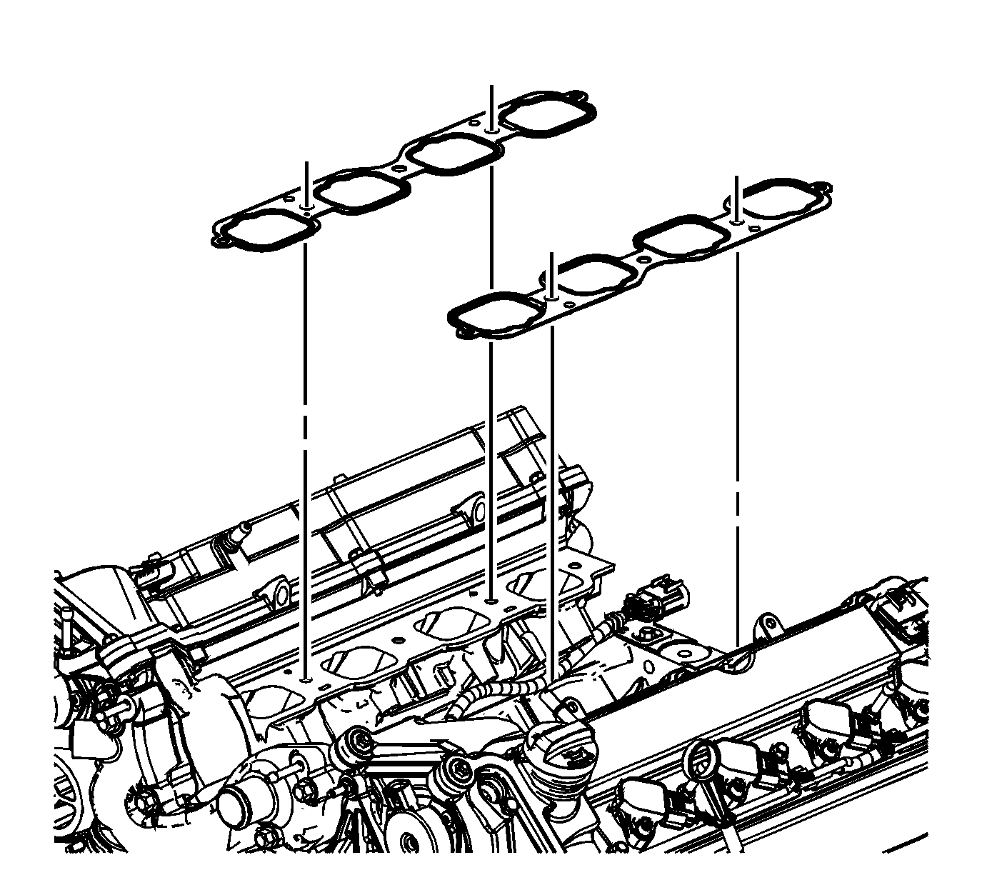
- Install the NEW supercharger gaskets.
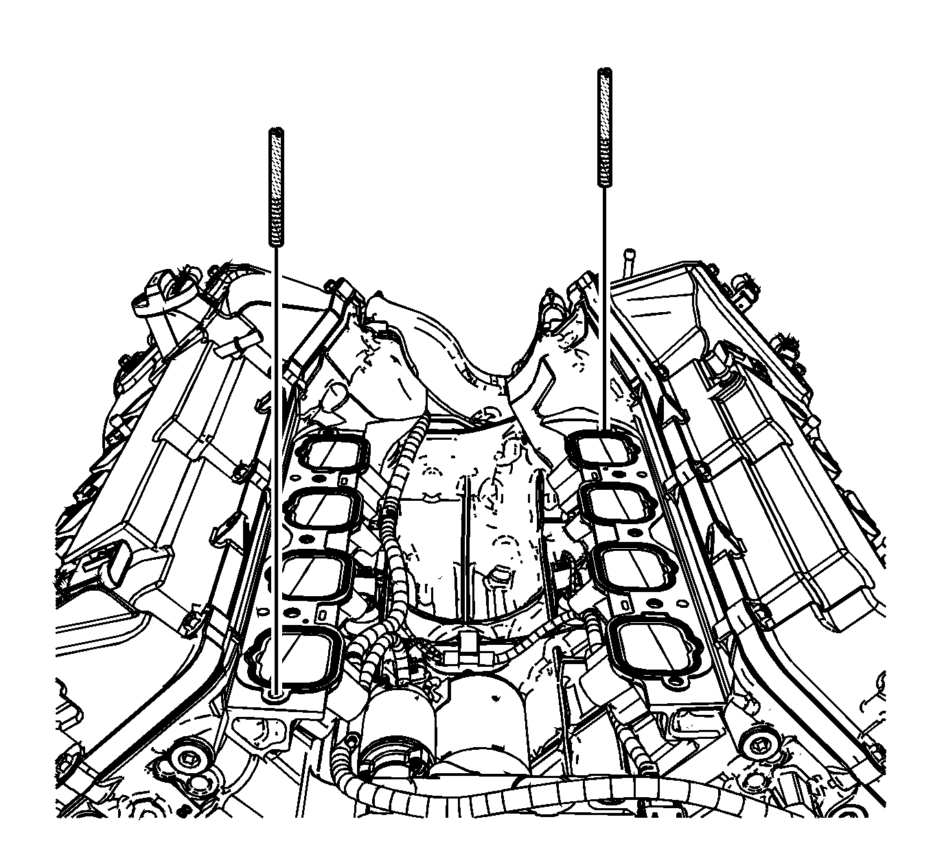
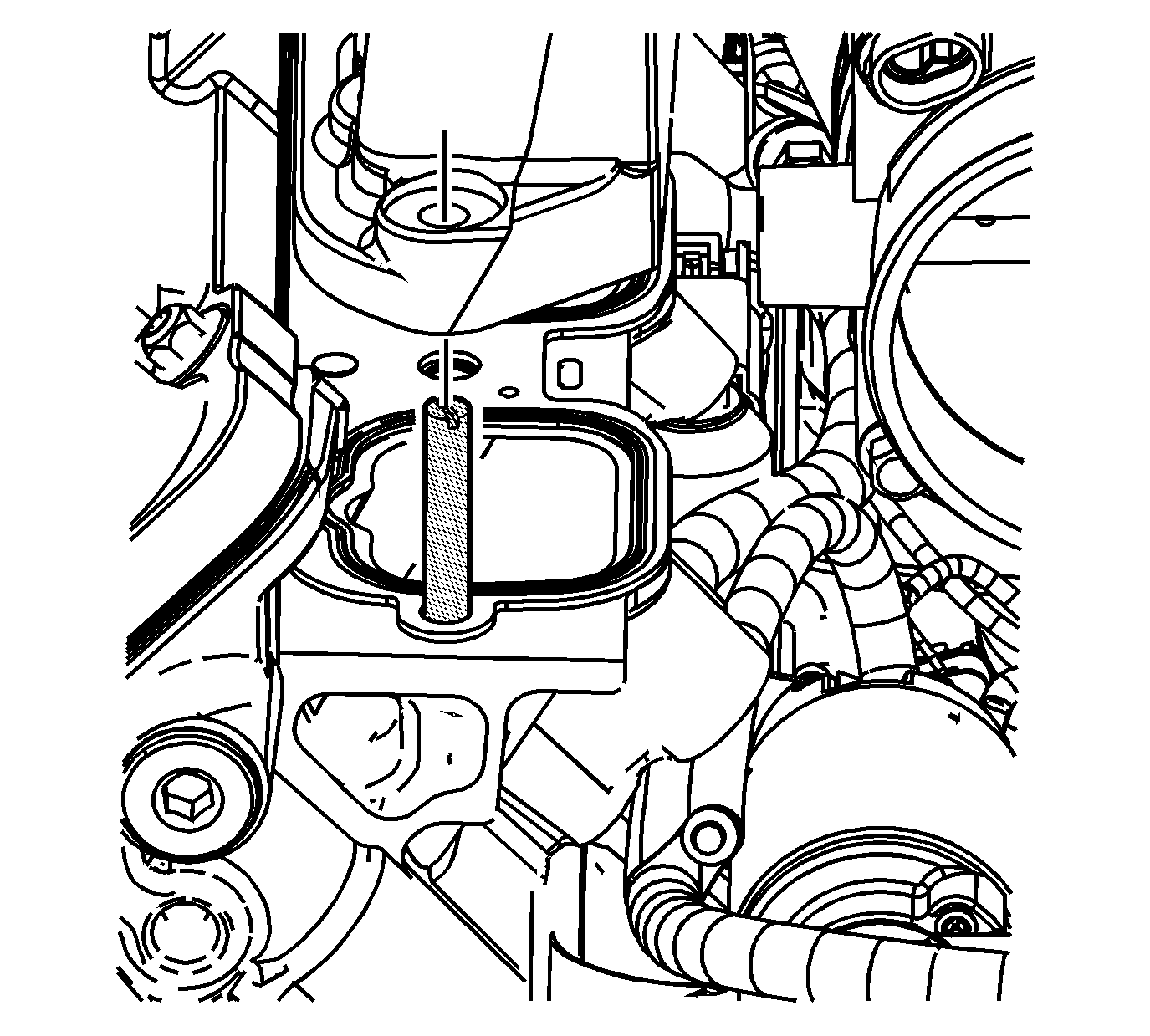
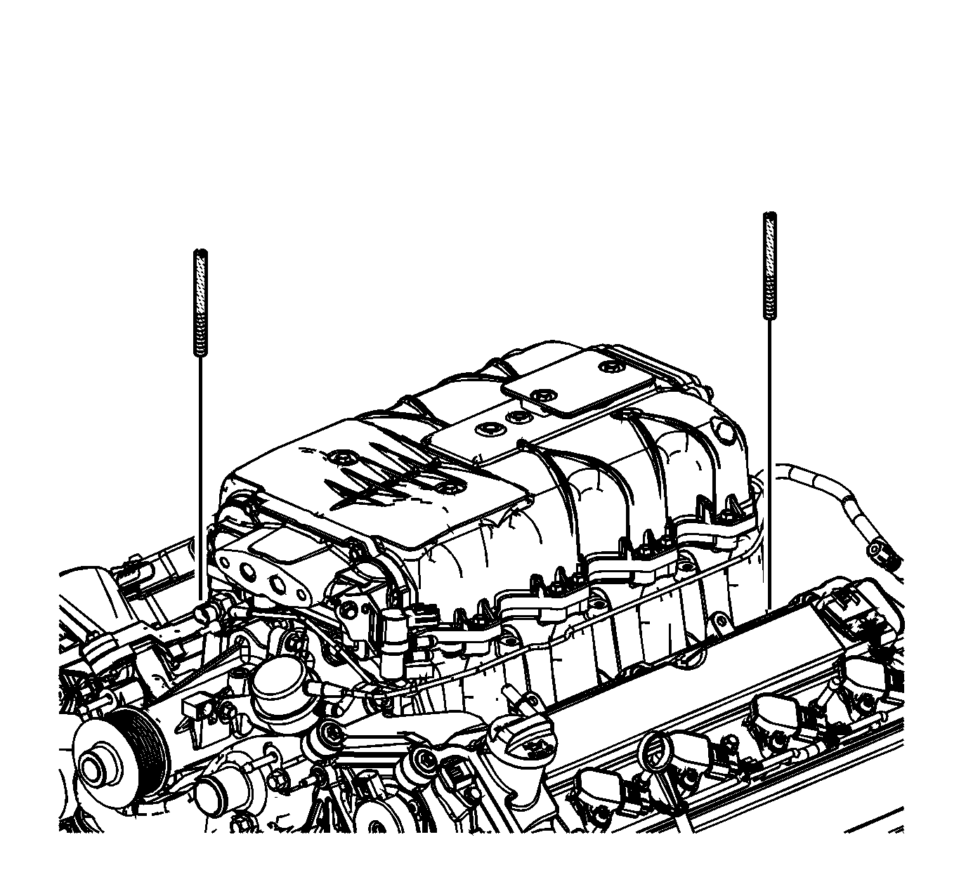
- Install the 8 mm (0.31 in) EN 46109 pins into cylinder head supercharger mounting bolt holes at opposing corners.
- Lift the supercharger assembly off of the table using appropriate lifting equipment.
- Remove the EN-47833 fixture from the supercharger.
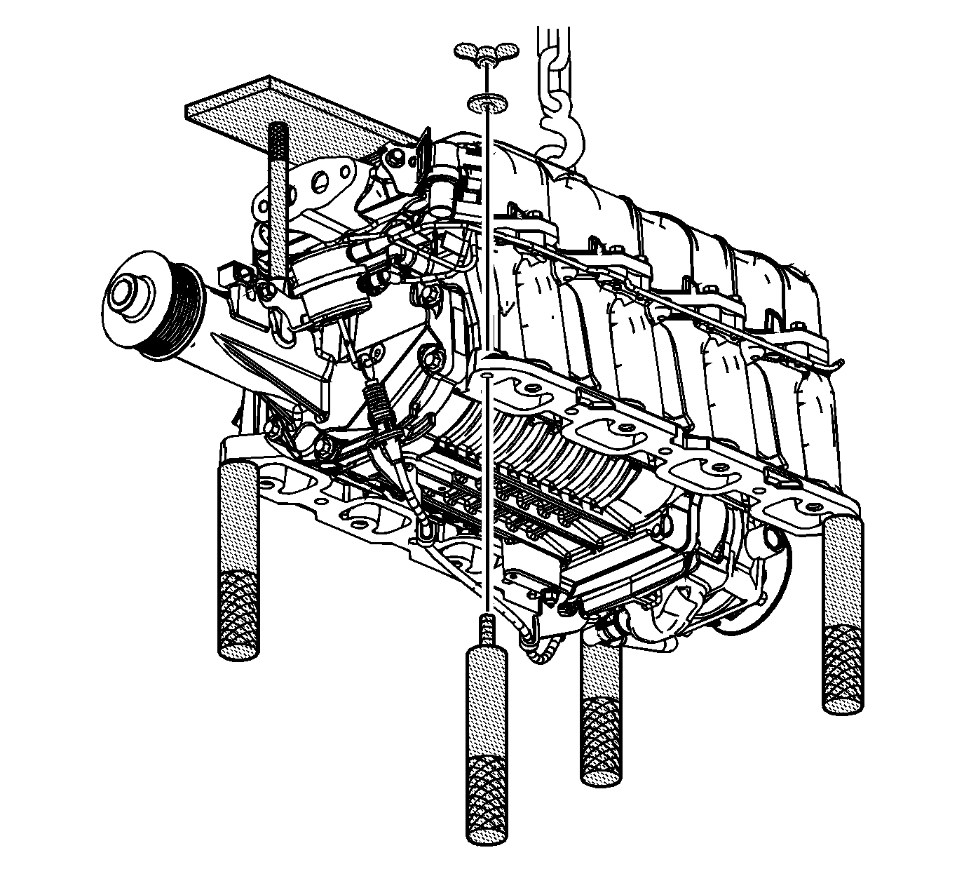
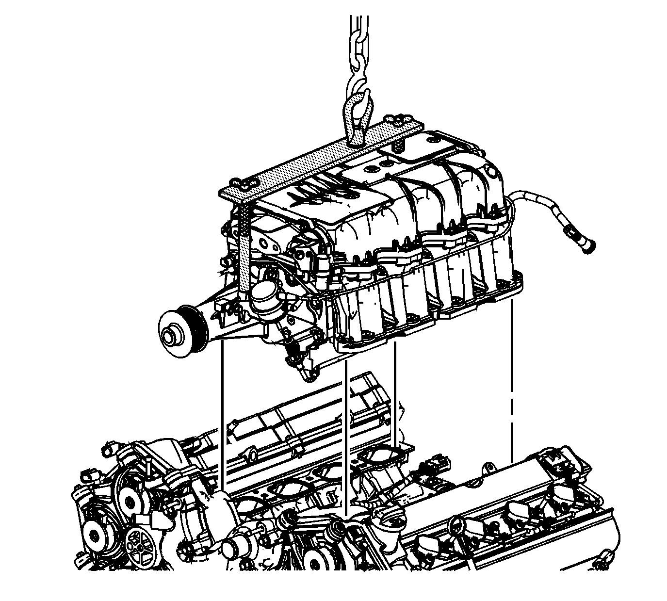
- Install the supercharger using the EN-47748 fixture with appropriate lifting equipment.
- As the supercharger is lowered into place carefully align the EN 46109 pins with the corner mounting holes of the supercharger.
- Remove the EN-47748 fixture from the supercharger.
- Remove the EN 46109 pins .
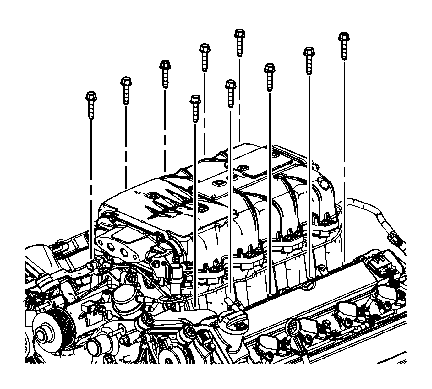
- Loosely install the supercharger bolts.
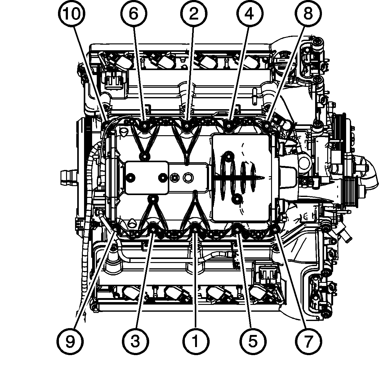
- Tighten the supercharger bolts in sequence as shown. Tighten the supercharger bolts in sequence to 25 N·m (18 lb ft).
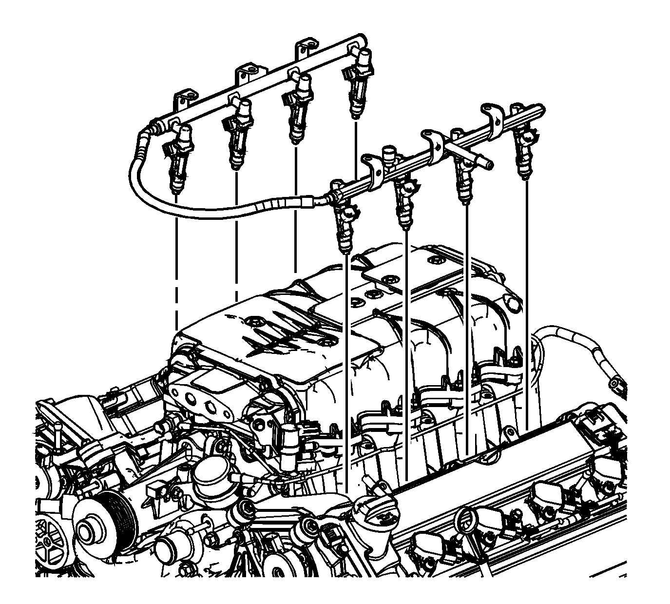
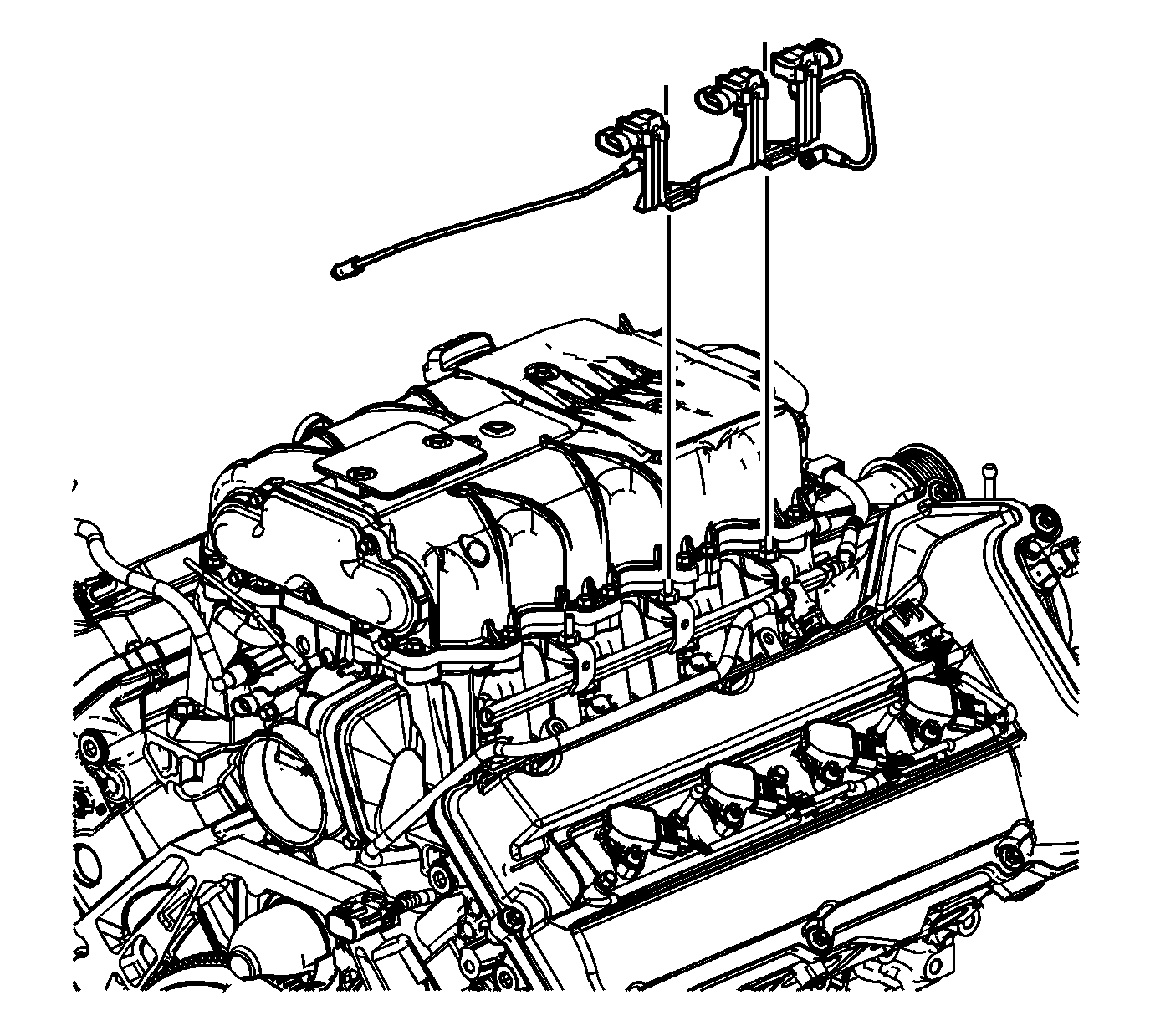
- Place the fuel injector rail assembly into position and align each fuel injector with the fuel injector bores in the supercharger.
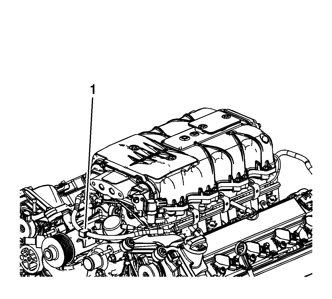
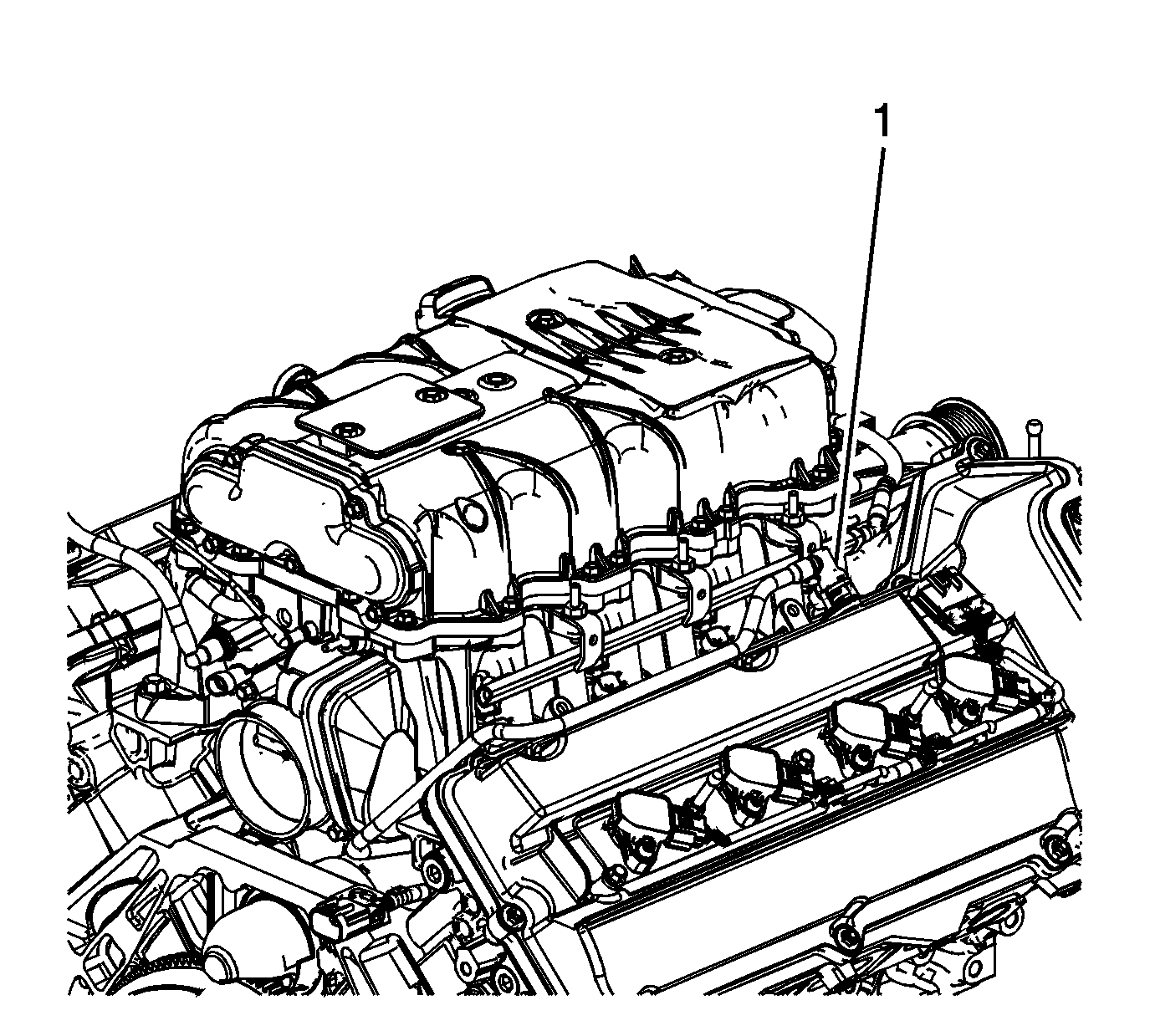
- Place the fuel injection rail crossover tube into the clip (1) and fasten.
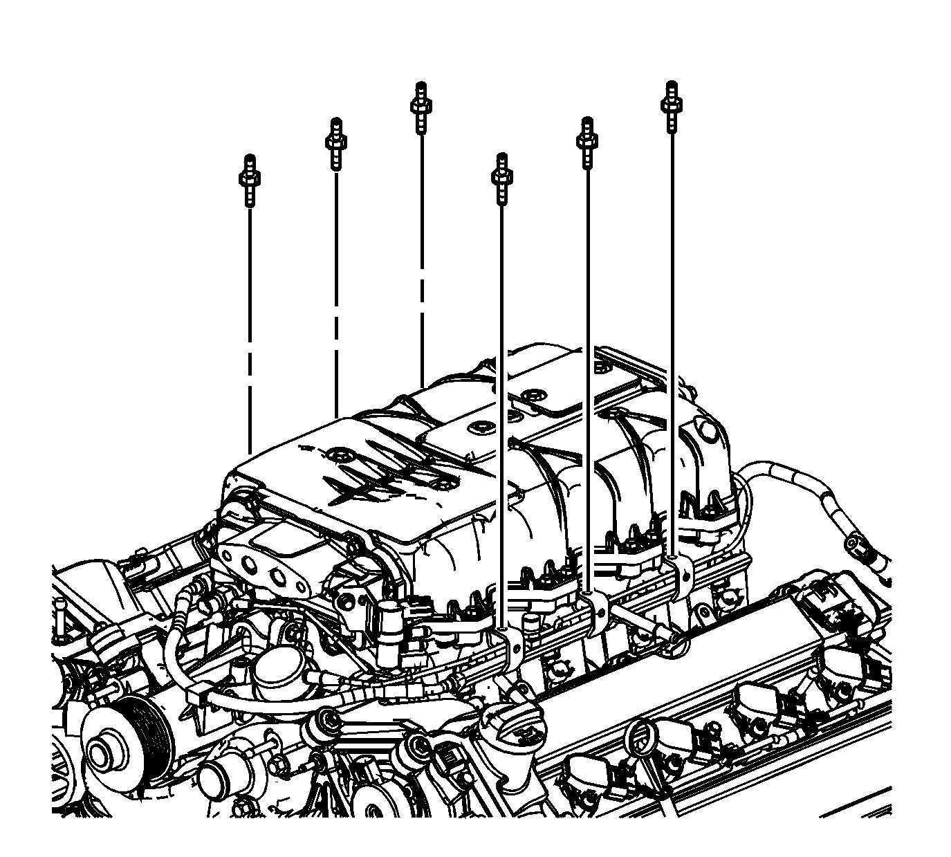
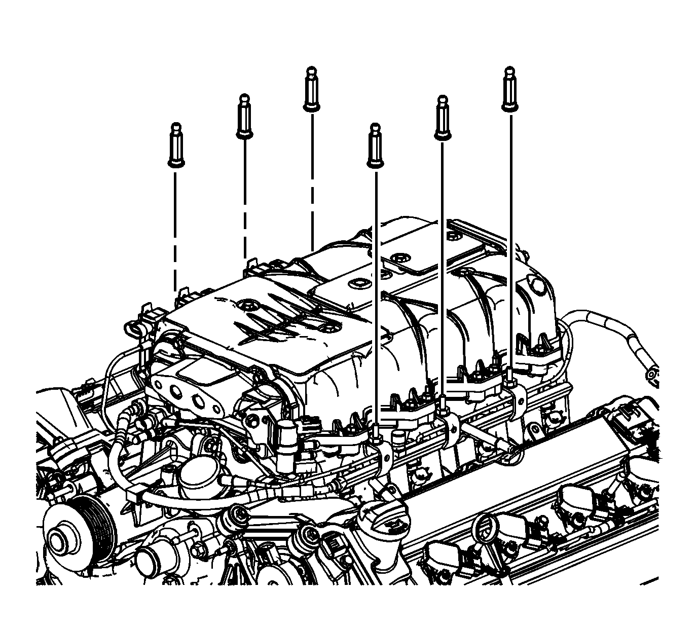
- Install the fuel injection rail studs and tighten to 10 N·m (89 lb in).
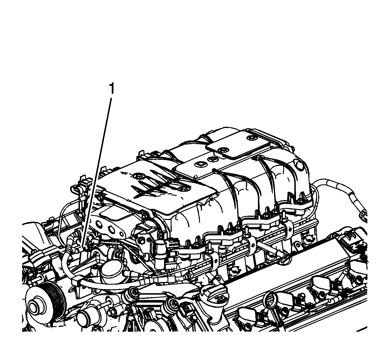
- Connect the dirty air positive crankcase ventilation (PCV) tube (1) to the right camshaft cover.
- Install the bracket with sensors and tubes.
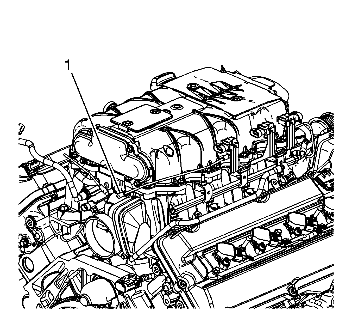
- Connect the supercharger inlet absolute pressure sensor vacuum tube connection (1) to the supercharger fitting.
- Connect the manifold absolute pressure (MAP) sensor vacuum tube connection (1) to the supercharger fitting.
- Install the fuel injector sight shield cover ball studs. Tighten the fuel injection sight shield cover ball studs to 10 N·m (89 lb in).
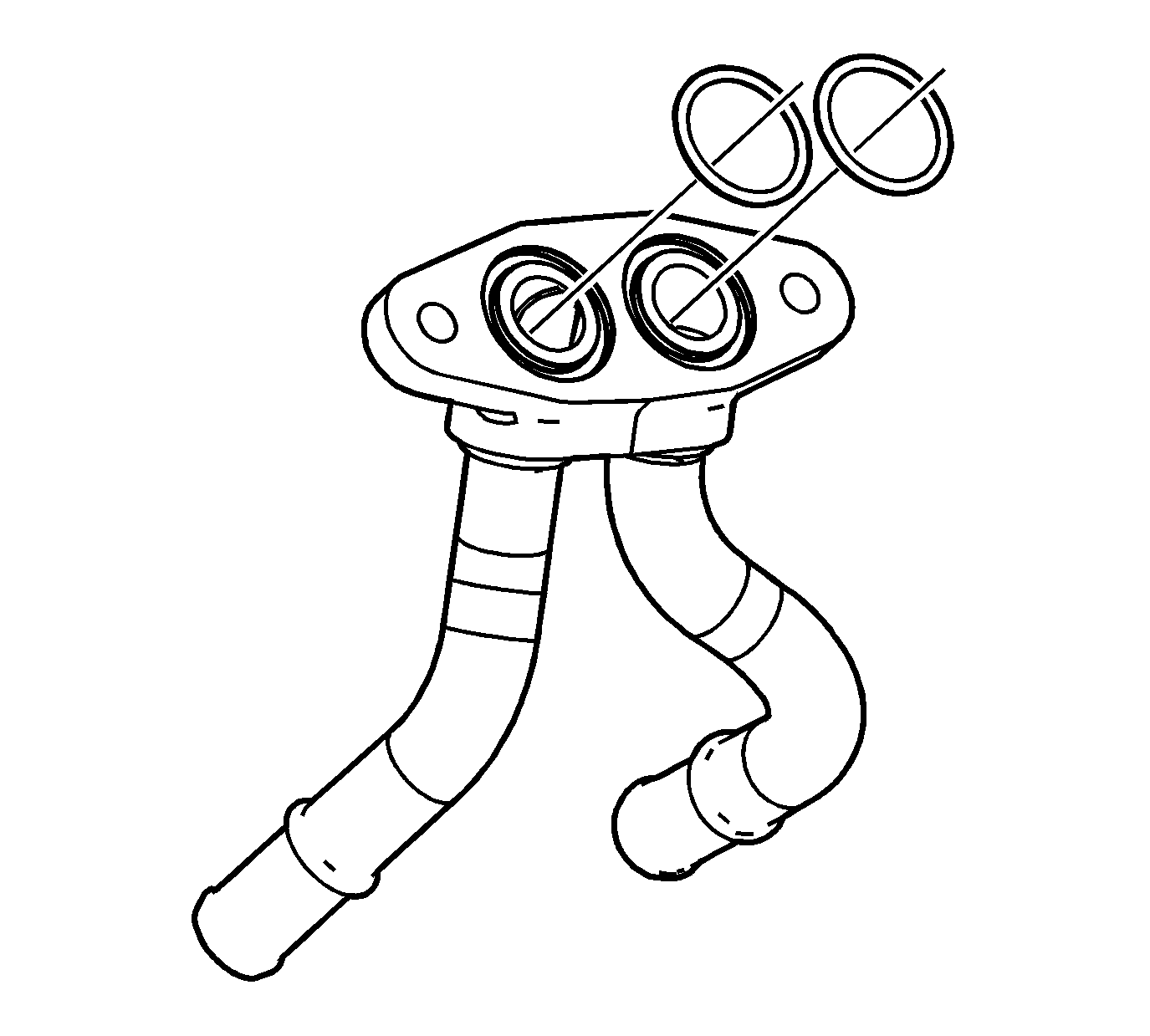
- Install the NEW charge air cooler coolant front manifold O-rings.
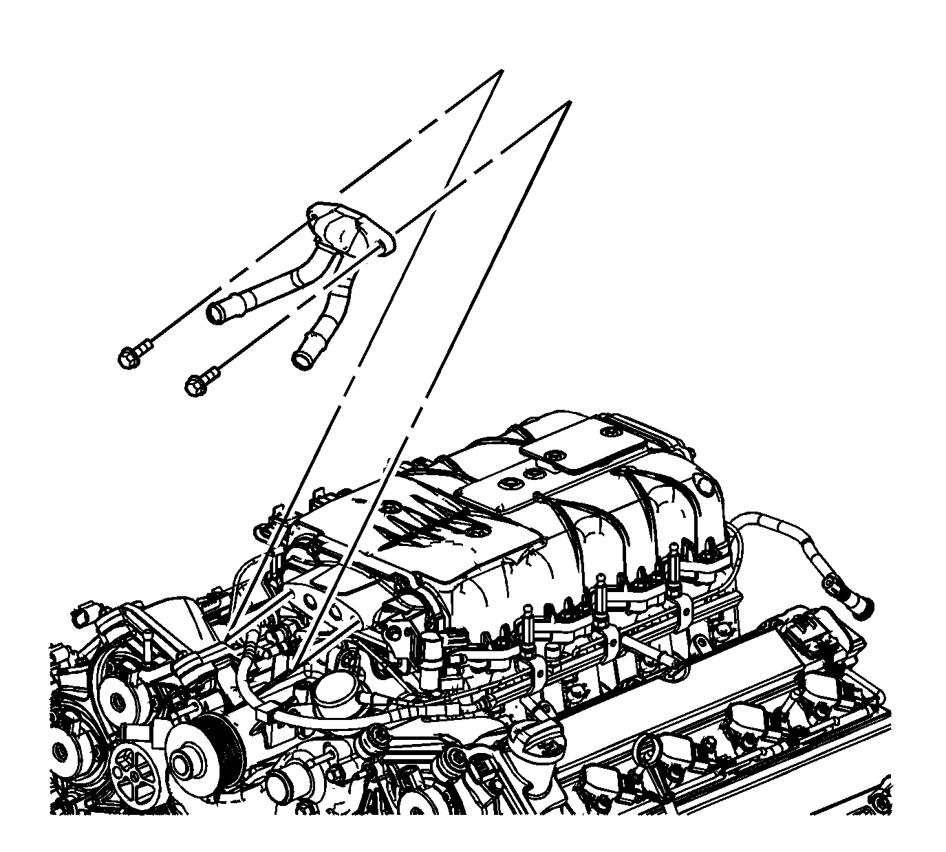
- Install the charge air cooler coolant front manifold.
- Install the charge air cooler coolant front manifold bolts and tighten to 25 N·m (18 lb ft).
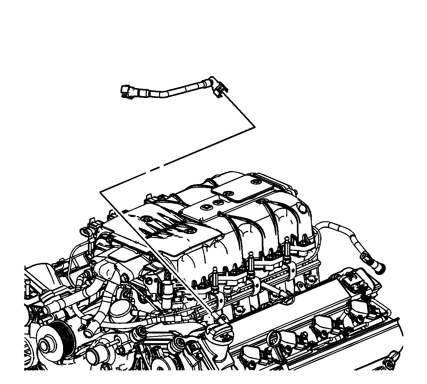
- Install and connect the clean air positive crankcase ventilation (PCV) tube to the left camshaft cover.
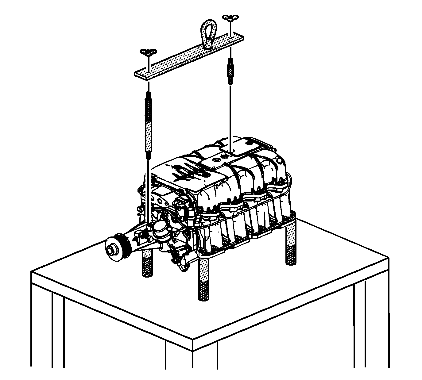
Warning: The supercharger must be lifted with the EN 47748. The weight of the supercharger assembly is approximately 34 kg (75 lb) and could cause injury if lifted by hand.
Caution: The supercharger must be lifted with the EN 47748. Damage could occur to the finish and/or components of the supercharger and surrounding engine or vehicle components.
Caution: Refer to Fastener Caution in the Preface section.
