For 1990-2009 cars only
Special Tools
| • | J 28467-86 Right Engine Lift Bracket |
| • | J 28467-87 Left Engine Lift Bracket |
Removal Procedure
- Drain the engine oil. Refer to Engine Oil and Oil Filter Replacement .
- Remove the powertrain. Refer to Powertrain Removal and Installation .
- Remove the left exhaust manifold assembly. Refer to Exhaust Manifold Replacement - Left Side .
- Remove the left engine mount bracket. Refer to Engine Mount Bracket Replacement - Left Side .
- Remove the drive belt tensioner. Refer to Drive Belt Tensioner Replacement .
- Remove the generator. Refer to Generator Replacement .
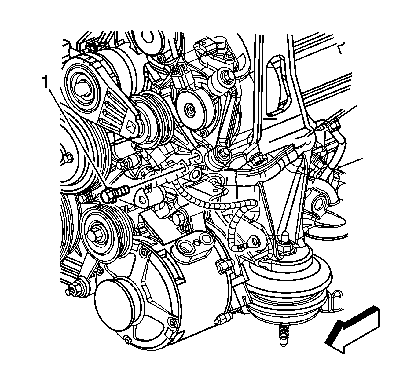
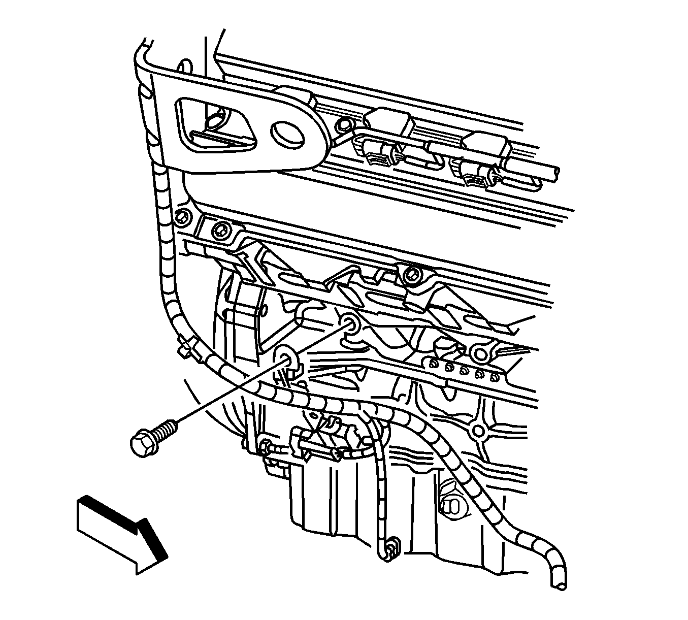
- Remove the bolt (1) securing the starter/generator harness clip to the front of the engine.
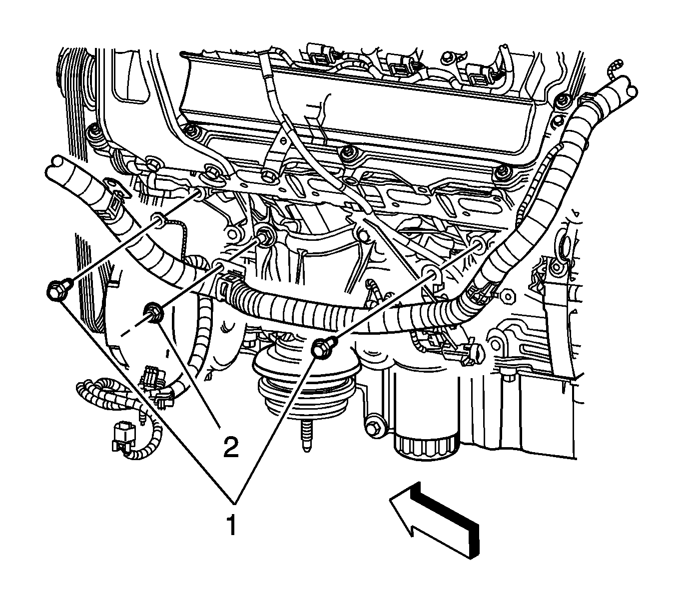
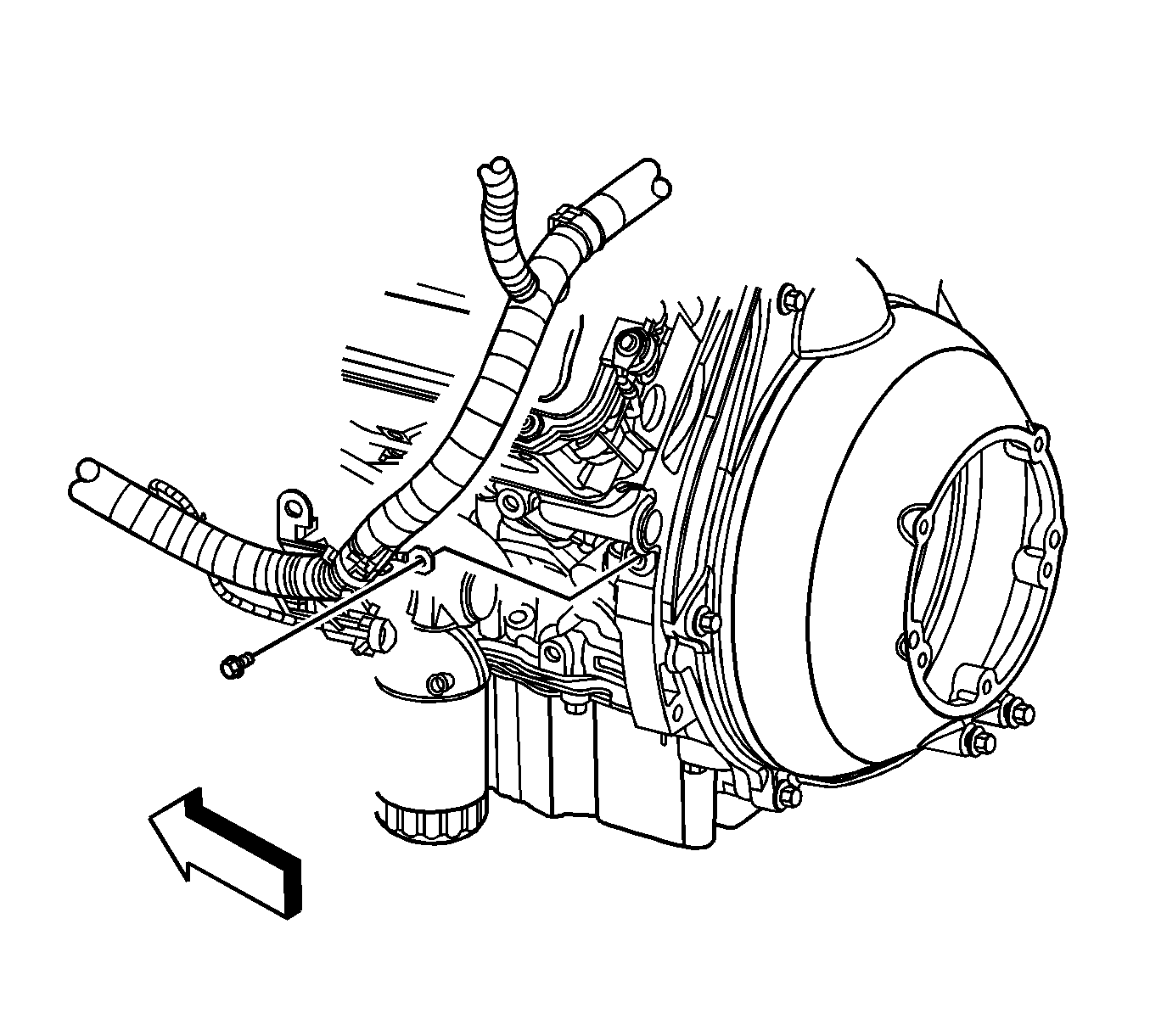
- Remove the bolts (1) and nut (2) securing the engine wiring harness to the left side of the engine.
- Remove the right exhaust manifold assembly. Refer to Exhaust Manifold Replacement - Right Side .
- Remove the right engine mount bracket. Refer to Engine Mount Bracket Replacement - Right Side .
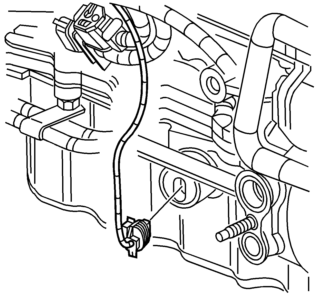
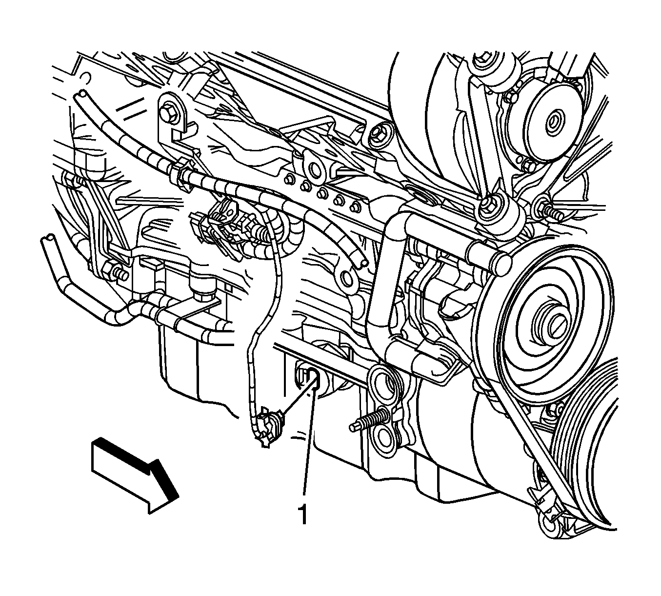
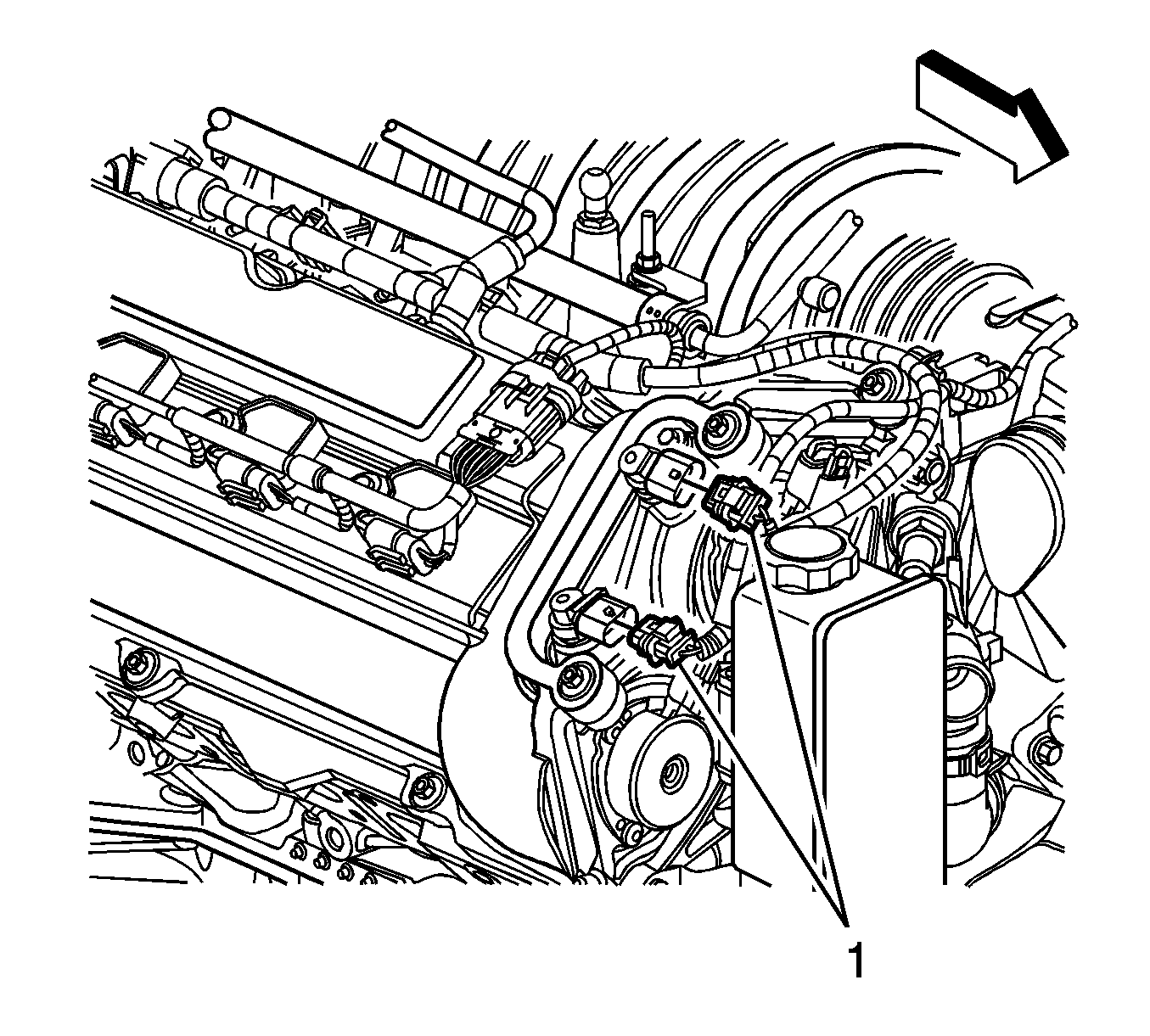
- Disconnect the electrical connector from the engine oil level sensor.
- Remove the power steering reservoir . Refer to Power Steering Fluid Reservoir Replacement .
- Remove the air conditioning compressor and bracket. Refer to Air Conditioning Compressor Replacement .
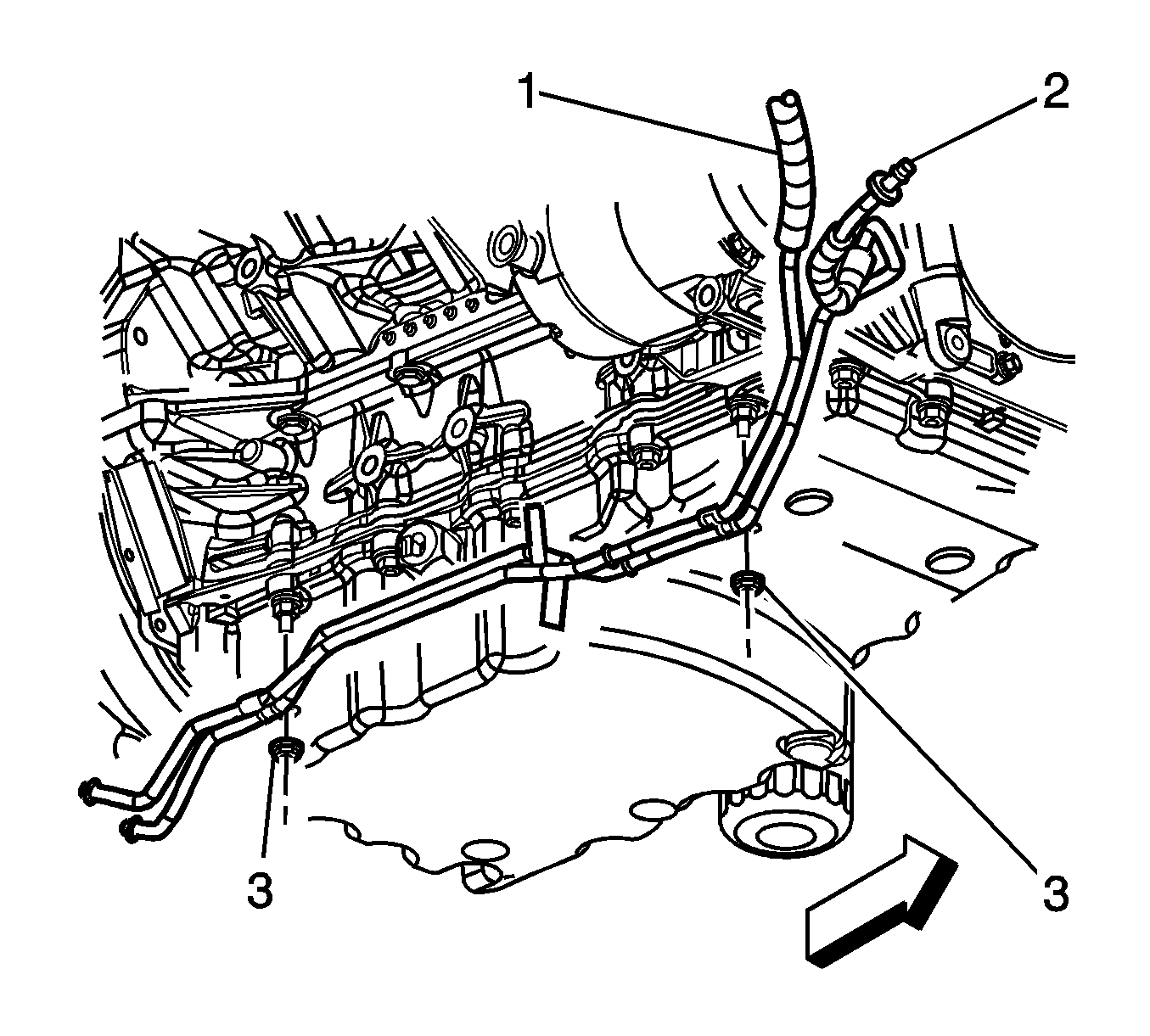
- Remove the transmission cooler line nut (3). Refer to Transmission Fluid Cooler Upper Pipe Assembly Replacement and Transmission Fluid Cooler Lower Pipe Assembly Replacement - Transmission to Auxiliary Cooler .
- Remove the coolant temperature sensor. Refer to Engine Coolant Temperature Sensor Replacement .
- Remove the bolts (1) and nut (2) securing the wiring harness to the engine.
- Remove the engine wiring harness.
- Remove the throttle body assembly. Refer to Throttle Body Assembly Replacement .
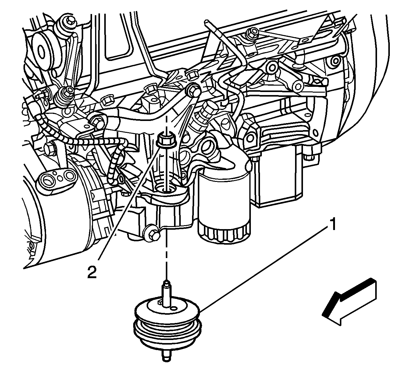
- Remove the engine mount (1).
- Remove the left ignition module assembly. Refer to Ignition Coil Module Replacement - Left Side .
- Remove the right ignition module assembly. Refer to Ignition Coil Module Replacement - Right Side .
- Remove the starter motor from the engine. Refer to Starter Replacement .
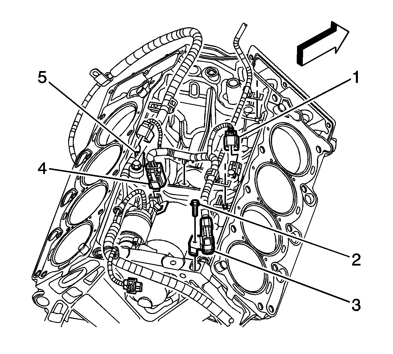
- Disconnect the electrical connector (5) from the left-hand knock sensor.
- Disconnect the electrical connector (1) from the right-hand knock sensor.
- Disconnect the electrical connector from the crank sensor (4).
- Remove the bolt (2) securing the wiring harness (3) to the engine.
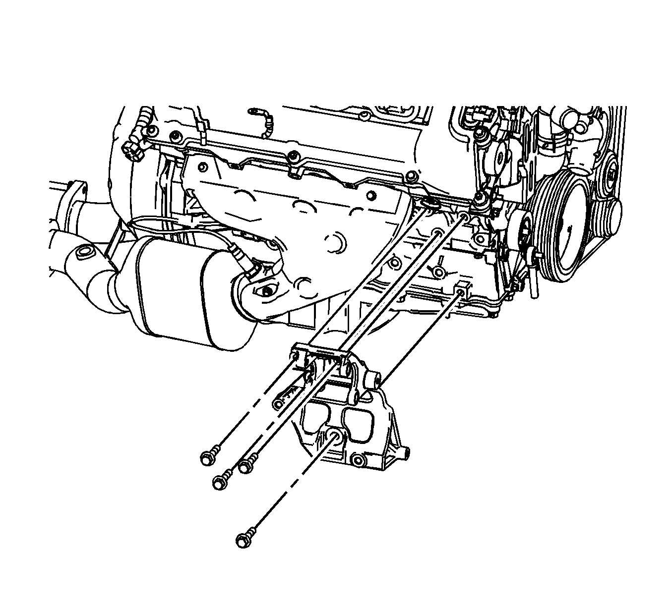
- Remove the driveline support bolts.
- Insert a flat-headed screwdriver, or similar tool, between the driveline support and the flywheel housing, then separate the driveline assembly from the engine.
- Slowly pull the driveline support assembly away from the engine.
- Install the J 28467-86 and J 28467-87 to the engine.
- Install an engine hoist to the J 41798 .
- Remove the flywheel housing bolts.
- Remove the flywheel housing from the engine.
- Remove the engine from the lift table.
- Remove the engine hoist.
- Remove the engine lift brackets.
Warning: Refer to Battery Disconnect Warning in the Preface section.
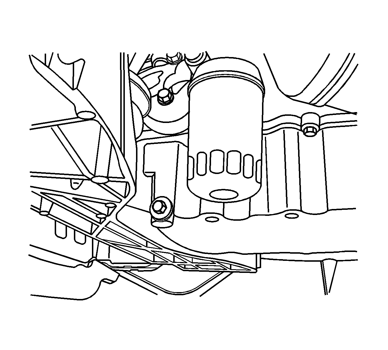
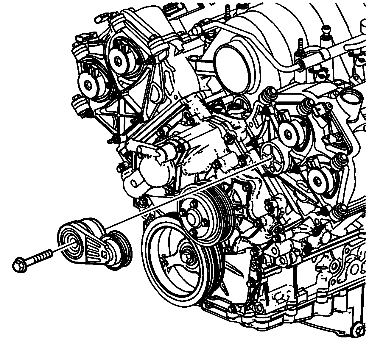

Note: Visually inspect the transmission wiring harness to ensure detachment from the engine.
Installation Procedure
- Using an engine hoist, install the replacement engine on an engine stand.
- Install the transmission oil cooler pipes (1) to engine. Refer to Transmission Fluid Cooler Upper Pipe Assembly Replacement and Transmission Fluid Cooler Lower Pipe Assembly Replacement - Transmission to Auxiliary Cooler .
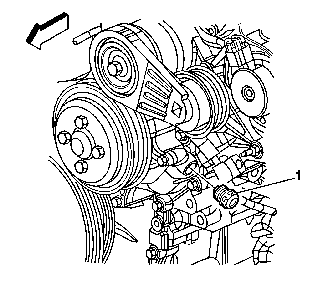
- Connect the harness to the low lever oil switch (1).
- Install the bolt through the engine harness clip and secure to the right side of the engine and tighten to 35 N·m (26 lb ft) .
- Connect the left rear engine harness ground terminal to the engine. Tighten the bolt to 12 N·m (106 lb in) .
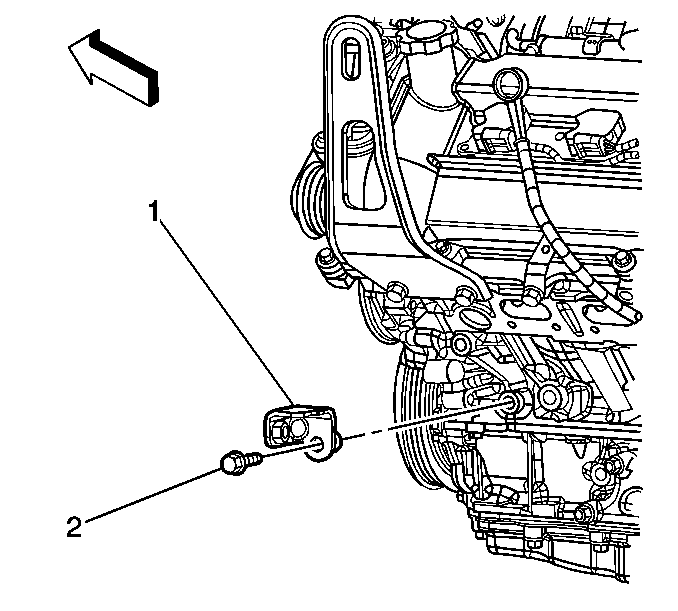
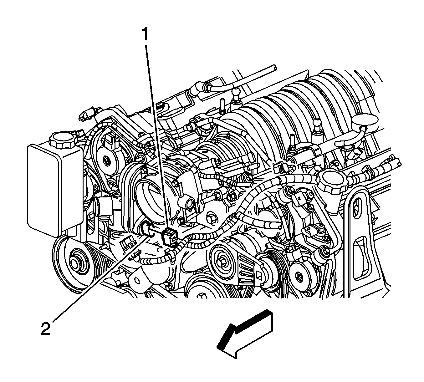
- Connect the harness (1) to the oil pressure sensor (2).
- Install the air conditioning/power steering bracket to the engine assembly. Refer to Air Conditioning Compressor Replacement .
- Install the power steering pump reservoir to the engine. Refer to Power Steering Fluid Reservoir Replacement .
- Install the drive belt tensioner. Refer to Drive Belt Tensioner Replacement .
- Install the generator coolant inlet hose fitting (1) and tighten the bolt (2) to 25 N·m (18 lb ft) .
- Install the generator rear brace (1) to the engine. Tighten the bolt to 50 N·m (37 lb ft) .
- Install the generator stud to the engine lower crankcase and tighten to 12 N·m (106 lb in) .
- Install the generator . Refer to Generator Replacement .
- Connect the harness connector (5) to the left knock sensor.
- Connect the harness connector (1) to the right knock sensor.
- Connect the harness connector (4) to the crank sensor.
- Install the bolt (2) through the harness bracket and tighten to 10 N·m (89 lb in) .
- Install the starter. Refer to Starter Replacement .
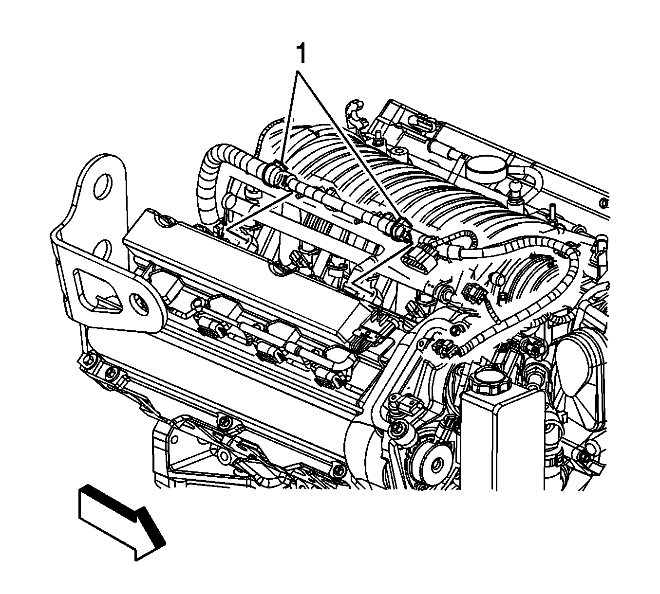
- Attach the right side upper wiring harness (1) as shown.
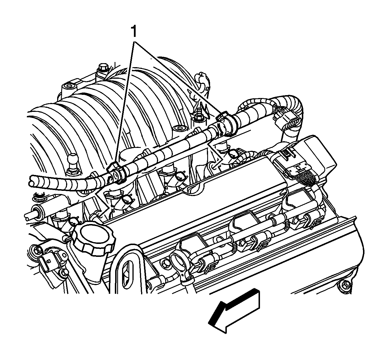
- Attach the left side upper wiring harness (1) to the cam cover as shown.
- Connect the engine harness to the right camshaft position sensors (1).
- Connect the engine wiring harness to the purge valve solenoid.
- Connect the engine wiring harness to the left camshaft position sensors.
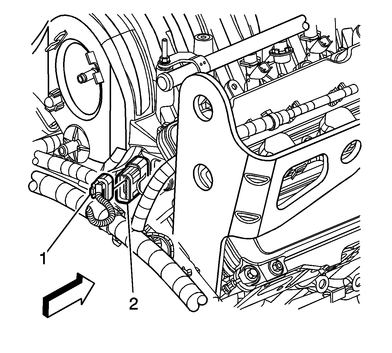
- Connect the jumper harness (1) to the engine harness sensor (2) as shown.
- Install the left ignition module assembly. Refer to Ignition Coil Module Replacement - Left Side .
- Install the right ignition module assembly. Refer to Ignition Coil Module Replacement - Right Side .
- Install the coolant temperature sensor. Refer to Engine Coolant Temperature Sensor Replacement .
- Connect the harness to the throttle position sensor (1).
- Install the left engine mount bracket to the engine. Refer to Engine Mount Bracket Replacement - Left Side .
- Secure the wiring harness to the engine.
- Install the right engine mount bracket to the engine. Refer to Engine Mount Bracket Replacement - Right Side .
- Install an engine hoist to the engine.
- Remove the engine from the engine stand.
- Install the flywheel housing and bolts. Refer to Engine Flywheel Replacement .
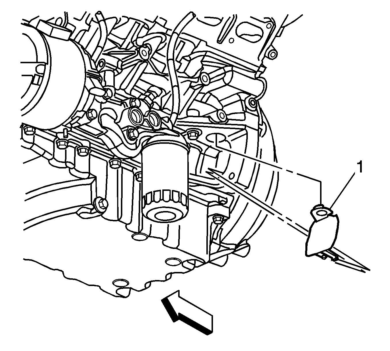
- Install the flywheel housing (1) left side cover to the engine.
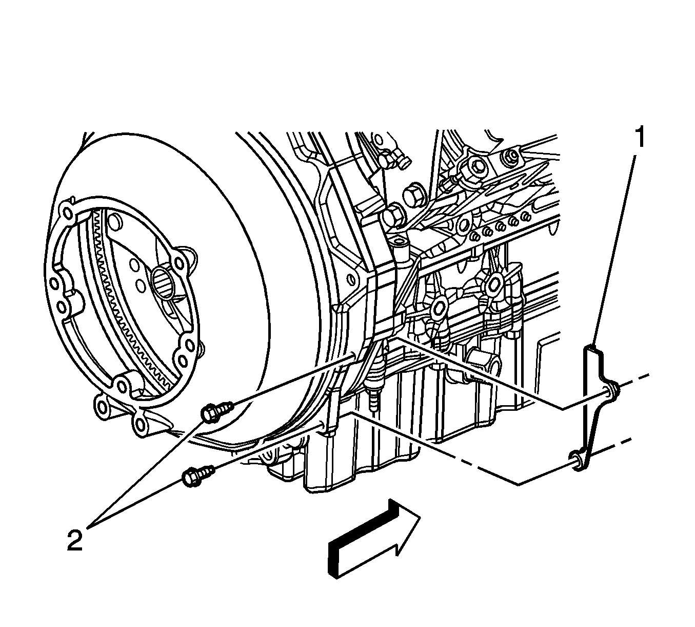
- Install the engine closeout cover to the right side of the bell housing. Tighten the bolts (2) to 10 N·m (89 lb in).
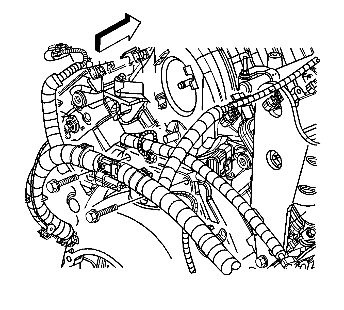
- Install the engine wiring harness to the engine by inserting the bolts through the harness clips and into the bell housing. Tighten the bolts to 50 N·m (37 lb ft) .
- Install the engine into the front cradle.
- Remove the engine lift brackets.
- Install the exhaust manifold studs to the right cylinder head and tighten to 6 N·m (53 lb in) .
- Install the exhaust manifold studs to the left cylinder head and tighten to 6 N·m (53 lb in) .
- Install the right exhaust manifold assembly to the engine. Refer to Exhaust Manifold Replacement - Right Side .
- Install the left exhaust manifold assembly to the engine. Refer to Exhaust Manifold Replacement - Left Side .
- Install the evaporator emission canister purge tube assembly to the engine.
- Install the powertrain. Refer to Powertrain Removal and Installation .
- Fill the oil system to the proper level.

Caution: Refer to Fastener Caution in the Preface section.
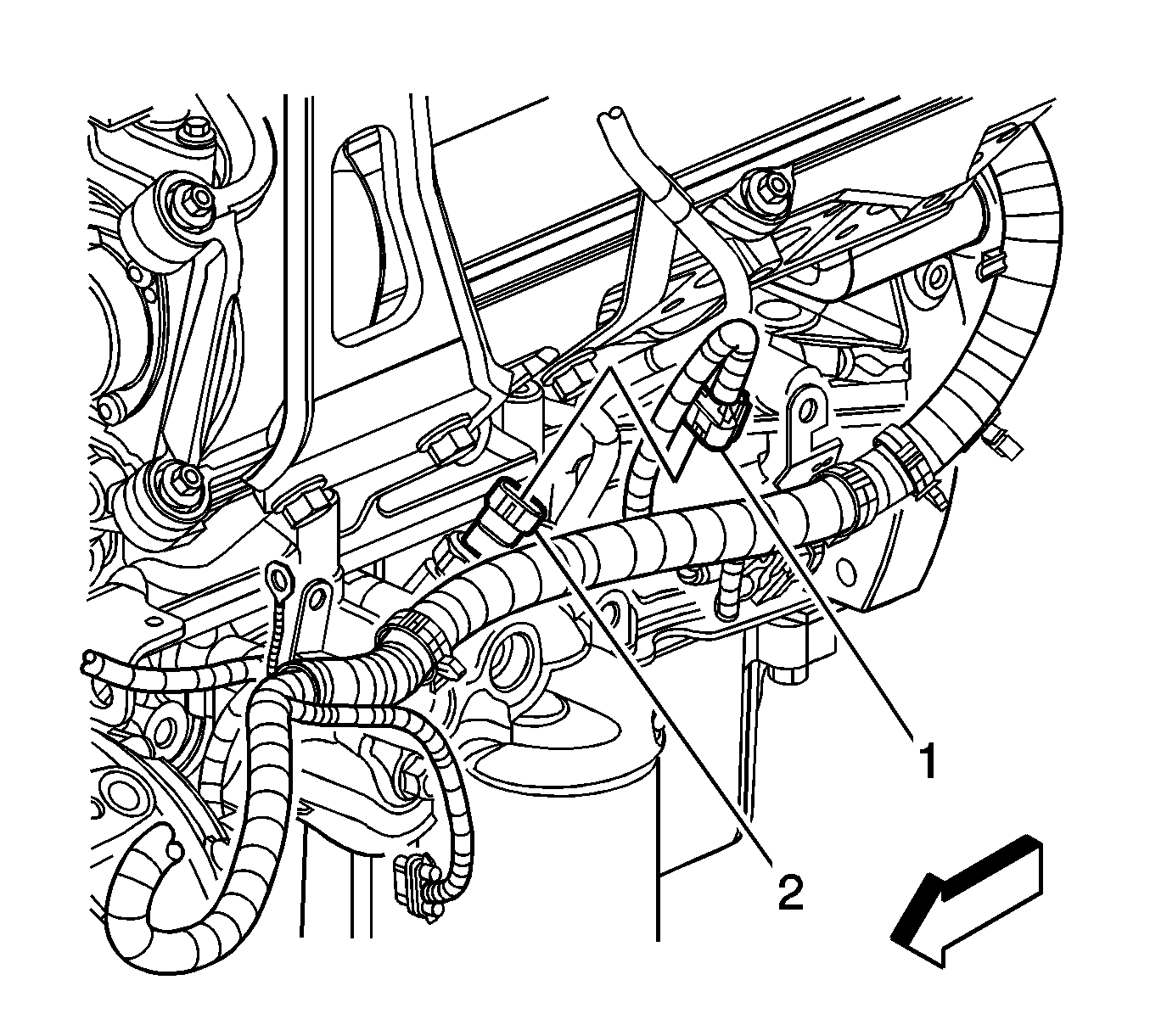


| • | Tighten the bolts (1) to 35 N·m (26 lb ft) . |
| • | Tighten the nut (2) to 35 N·m (26 lb ft) . |
