For 1990-2009 cars only
Removal Procedure
- Remove the engine sight shield. Refer to Intake Manifold Sight Shield Replacement.
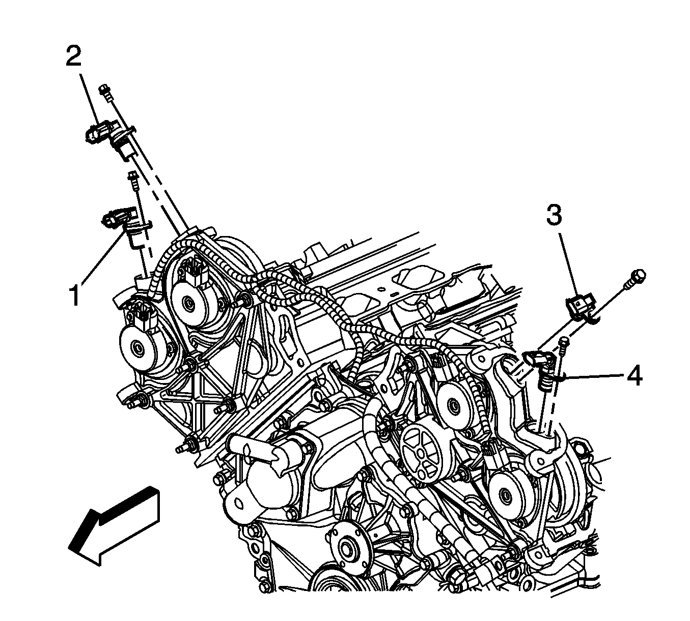
- Disconnect the electrical connector from the left bank exhaust camshaft position sensor (4).
- Remove the camshaft position sensor retaining bolt.
- Remove the left bank exhaust camshaft position sensor (4).

Note: When disconnecting more than one sensor, mark the connectors to ensure correct installation. The electrical connectors are physically interchangeable, however, they must be installed to the correct sensor.
Installation Procedure
- Lubricate the camshaft position sensor O-ring with engine oil.
- Install the left bank exhaust camshaft position sensor (4) and retaining bolt and tighten to 10 N·m (89 lb in).
- Connect the camshaft position sensor electrical connector.
- Operate the engine and inspect the camshaft position sensor for engine oil leaks.
- Install the engine sight shield. Refer to Intake Manifold Sight Shield Replacement.

Note: Inspect the camshaft position sensor O-ring for wear or damage. If a problem is found, replace the O-ring.
Caution: Refer to Fastener Caution in the Preface section.
