For 1990-2009 cars only
Special Tools
J 39400-A Halogen Leak Detector
Removal Procedure
- Recover the refrigerant from the A/C system. Refer to Refrigerant Recovery and Recharging.
- Remove the A/C compressor hose assembly. Refer to Compressor Hose Assembly Replacement.
- Remove the stabilizer shaft. Refer to Stabilizer Shaft Replacement.
- Remove the RH lower shock absorber mounting bolts. Refer to Shock Absorber Replacement.
- Separate the RH upper ball joint from the RH upper control arm. Refer to Upper Control Arm Replacement.
- Remove the LH wheel and tire and wheel. Refer to Tire and Wheel Removal and Installation.
- Remove the LH lower shock absorber mounting bolts. Refer to Shock Absorber Replacement.
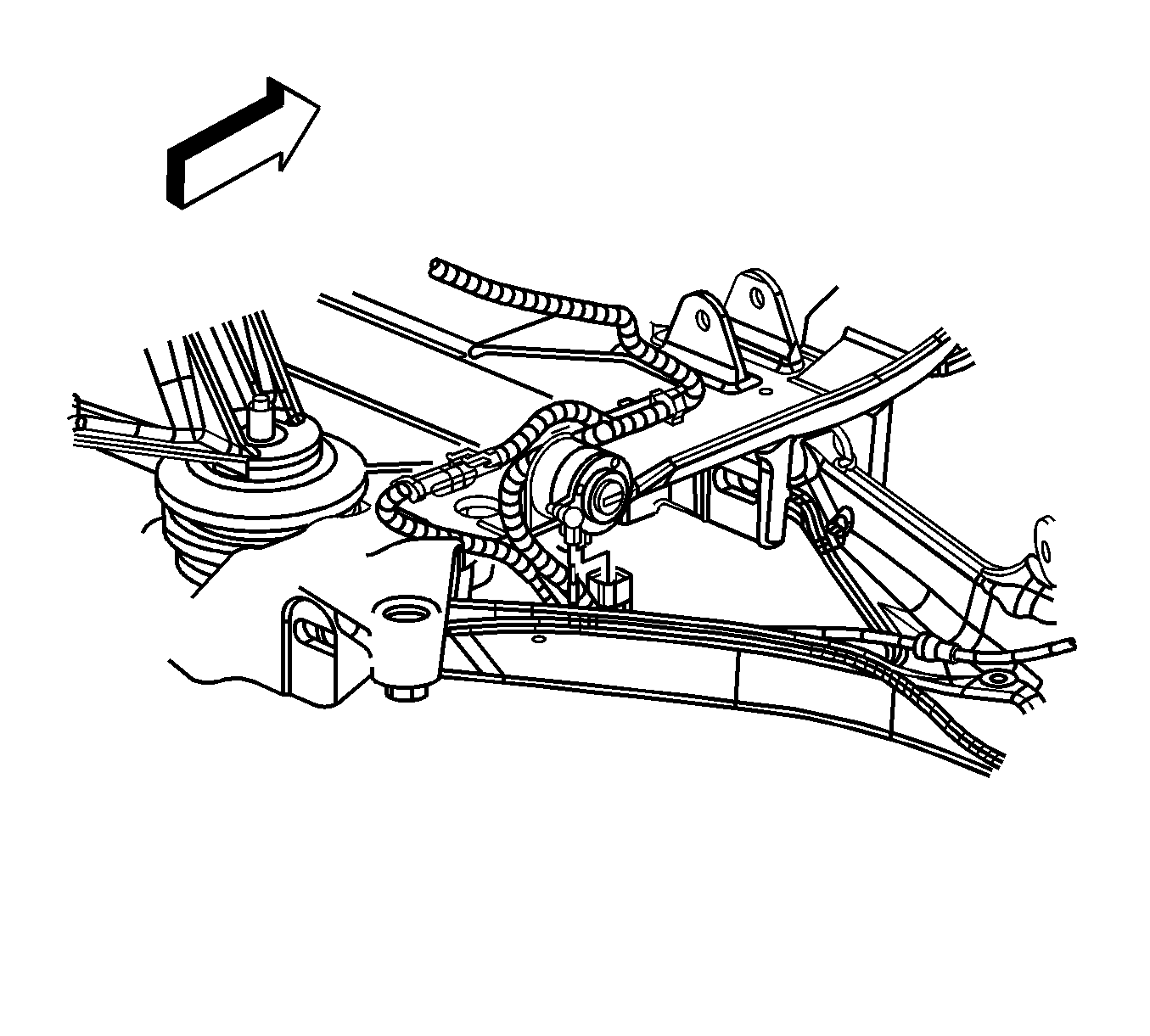
- Disconnect the RH ESC position sensor harness connector.
- Disconnect the RH ESC sensor link from the control arm link stud.
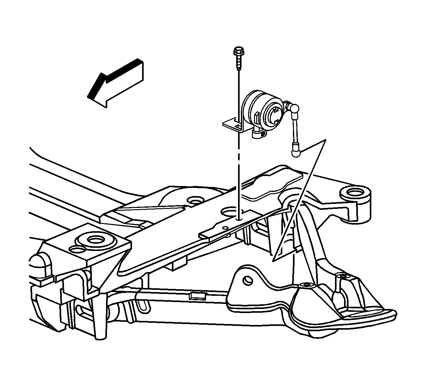
- Remove the RH ESC position sensor mounting bolt.
- Remove the RH ESC position sensor from the vehicle.
- Remove the RH brake pipe to front suspension crossmember mounting bolt.
- Support the LH side of the front crossmember.
- Support the RH side of the front crossmember with a transmission jack.
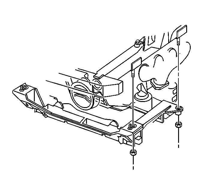
- Remove the front crossmember mounting nuts.
- Lower the LH side of the front crossmember approximately 0.375 in (10.0 mm).
- Lower the RH side of the front crossmember approximately 2.00 in (51.0 mm).
- Disconnect the A/C compressor electrical connector.
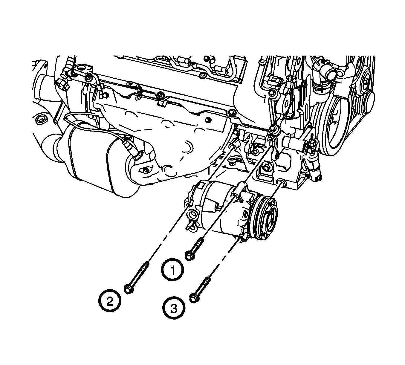
- Remove the A/C compressor mounting bolts (1, 2, 3).
- Remove the A/C compressor from the vehicle.
- If replacing the A/C compressor, balance the compressor. Refer to Air Conditioning Compressor Oil Balancing.
Note: The A/C compressor is removed through the RH front wheel house opening. It is necessary to lower the engine cradle assembly to allow adequate clearance during removal.


Note: Replacement A/C compressors are charged with PAG oil. Refer to Refrigerant System Capacities.
Installation Procedure
- Install the A/C compressor to the vehicle.
- Position the A/C compressor onto the A/C compressor bracket and install the A/C compressor mounting bolts (1, 2, 3) and torque in sequence and tighten to 50 N·m (37 lb ft).
- Connect the A/C compressor electrical connector.
- Raise the front crossmember into the proper position.
- Install the front crossmember mounting nuts and tighten to 110 N·m (81 lb ft).
- Remove the transmission jack from under the vehicle
- Install the RH brake pipe to front crossmember mounting bolt and tighten to 3 N·m (26 lb in).
- Install the ESC position sensor to the vehicle.
- Install the ESC position sensor mounting bolt and tighten to 3 N·m (26 lb in).
- Connect the ESC sensor link to the control arm link stud.
- Connect the RH ESC position sensor harness connector.
- Install the LH lower shock absorber mounting bolts. Refer to Shock Absorber Replacement.
- Install the LH wheel and tire and wheel. Refer to Tire and Wheel Removal and Installation.
- Install the RH upper ball joint to the RH upper control arm. Refer to Upper Control Arm Replacement.
- Install the RH lower shock absorber mounting bolts. Refer to Shock Absorber Replacement.
- Install the stabilizer shaft. Refer to Stabilizer Shaft Replacement.
- Install the compressor hose assembly. Refer to Compressor Hose Assembly Replacement.
- Evacuate and recharge the A/C system. Refer to Refrigerant Recovery and Recharging.
- Leak test the fittings of the A/C components using J 39400-A .
Caution: Refer to Fastener Caution in the Preface section.

Note: Finger tighten all the A/C compressor mounting bolts.


