For 1990-2009 cars only
Removal Procedure
- Turn the ignition switch to the OFF position.
- Apply and release the brake pedal several times until the pedal becomes firm to deplete the power vacuum brake booster vacuum reserve.
- Disconnect the battery negative cable. Refer to Battery Negative Cable Disconnection and Connection.
- Disconnect the brake fluid level indicator switch electrical connector.
- Remove the radiator surge tank. Refer to Radiator Surge Tank Replacement.
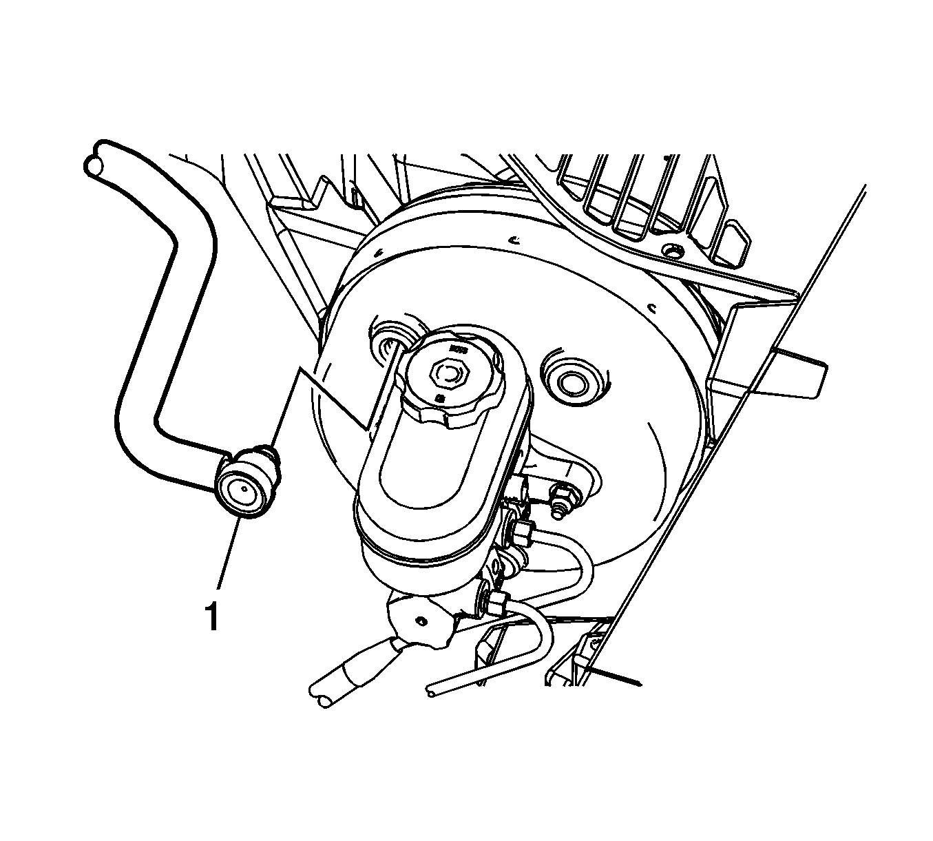
- Disconnect the vacuum brake booster check valve (1) from the power vacuum brake booster and position aside.
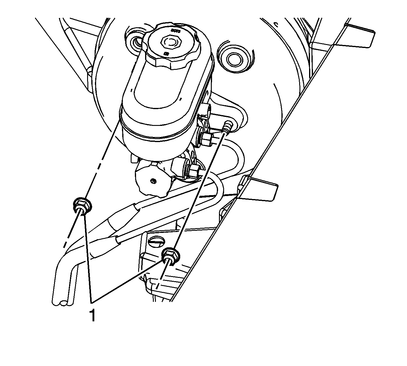
- Remove the master cylinder nuts (1).
- Without disconnecting the brake pipe fittings, remove the master cylinder and position aside.
- Remove the driver knee bolster panel. Refer to Driver Knee Bolster Panel Replacement.
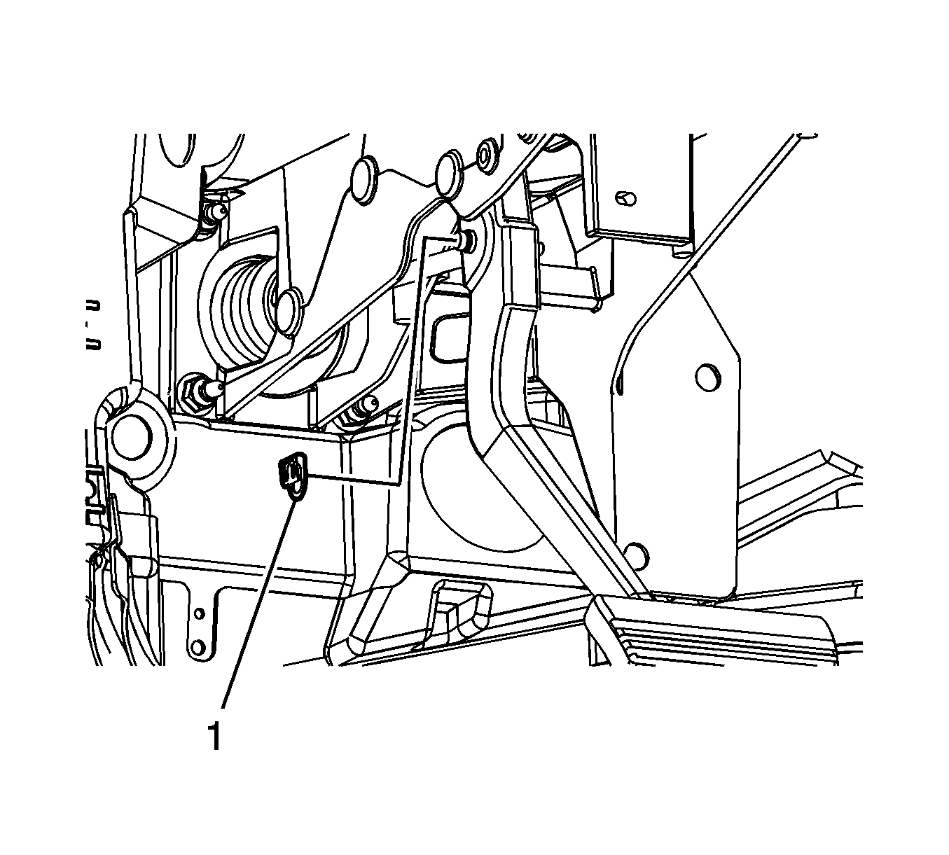
- Remove the brake booster pushrod clevis pin retainer (1).
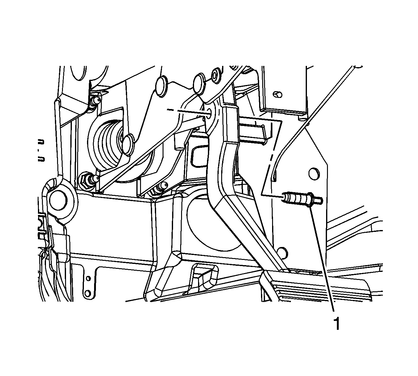
- Remove the brake booster pushrod clevis pin (1).
- Remove the power vacuum brake booster nuts (1).
- Remove the power vacuum brake booster (1).
- Remove the power vacuum brake booster gasket (2).
Secure the master cylinder in an upright position with heavy mechanics wire or equivalent.
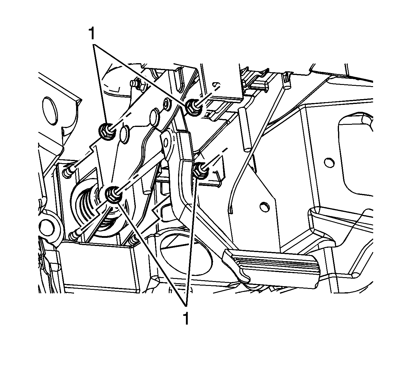
Note: The power vacuum brake booster is retained to the cowl with push-on nuts during assembly.
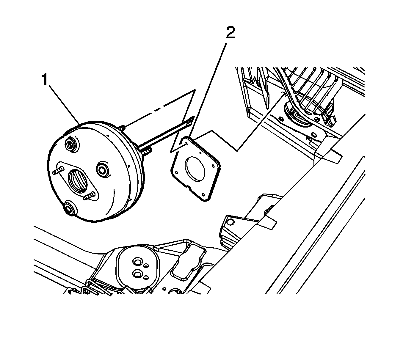
Move the power vacuum brake booster from side-to-side to release the booster studs from the push-on nuts.
Inspect the gasket for damage and replace, if necessary.
Installation Procedure
- Install the power vacuum brake booster (1) and the gasket (2) to the vehicle.
- Install the power vacuum brake booster nuts (1) and tighten to 27 N·m (20 lb ft).
- Install the brake booster pushrod clevis pin (1) to the brake pedal and the power vacuum brake booster pushrod.
- Install the brake booster pushrod clevis pin retainer (1).
- Install the driver knee bolster panel. Refer to Driver Knee Bolster Panel Replacement.
- Install the master cylinder to the power vacuum brake booster.
- Install the master cylinder nuts (1) and tighten to 18 N·m (13 lb ft).
- Connect the vacuum brake booster check valve (1) to the power vacuum brake booster.
- Install the radiator surge tank. Refer to Radiator Surge Tank Replacement.
- Connect the brake fluid level indicator switch electrical connector.
- Connect the battery negative cable. Refer to Battery Negative Cable Disconnection and Connection.

Caution: Refer to Fastener Caution in the Preface section.


Rotate the clevis pin retainer to ensure it is fully engaged in the clevis pin groove.


