4 WAL DIAGNOSTIC INFORMATION (ATTACHED TRAINING MANUAL)

Model and Year: 1990 CHEVROLET TRUCK WITH 4WAL BRAKE SYSTEM
The attached diagnostic manual (one copy) is being provided for your use until the 1990 Service Manual is available. This manual provides diagnostic information that can be used with or without the aid of a TECH 1 Scanner. This manual is not intended to negate the necessity of attending the General Motors training course covering the 4WAL brake system in any way.
II.1. Introduction
Application
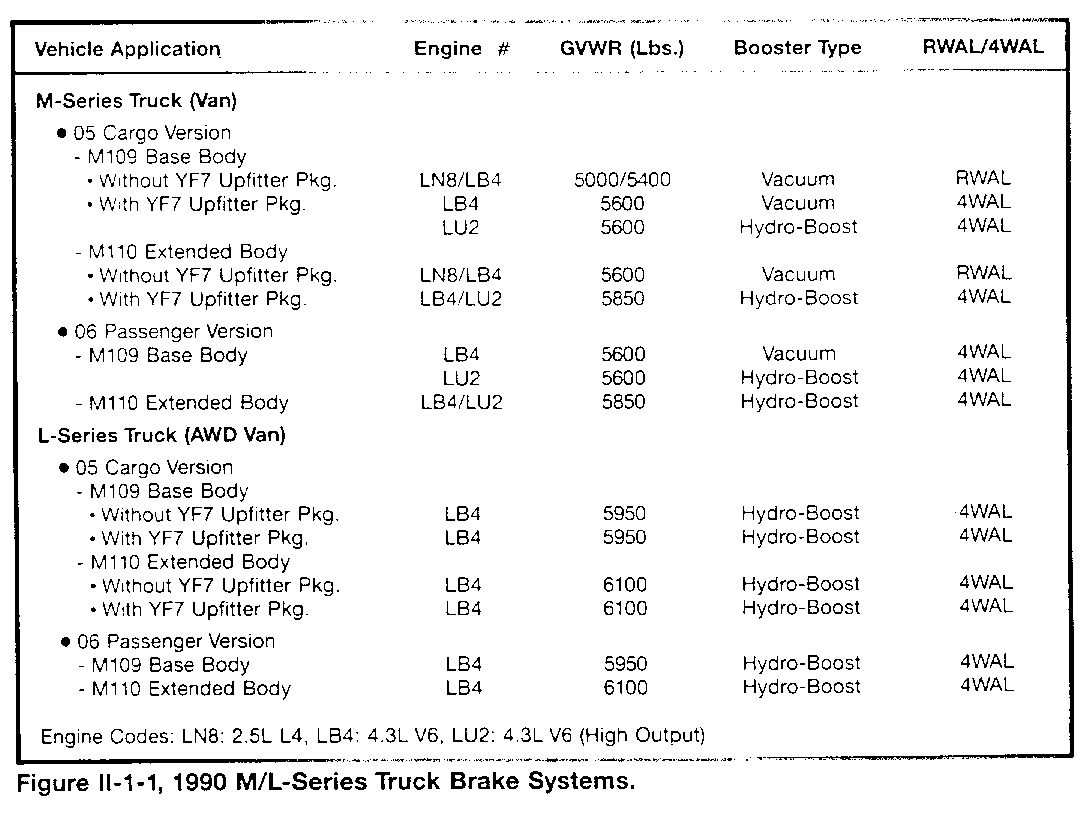
The Four-Wheel Antilock (4WAL) braking system is standard on these General Motors light-duty trucks:
1990 M-Series, base body 1990 M-Series, extended body 1990 AWD L-Series, base body 1990 AWD L-Series, extended body 1991 S-Series, four door 1991 T-Series, four door
Refer to Figure II-1-1 for more information about the 1990 M/L-Series brake systems.
DESIGN
A vehicle braking system uses driver brake pedal force to operate a hydraulic system, that operates the mechanical parts of the front-disc and rear-drum brakes. 4WAL provides additional electronic control of the LF, RF, and rear hydraulic channels independently, based on the action of an electronic controller that monitors LF, RF, LR, and RR wheel speed sensor signals. This assists the driver in maintaining control during braking. Refer to the Preface of this book for more information.
4WAL COMPONENTS
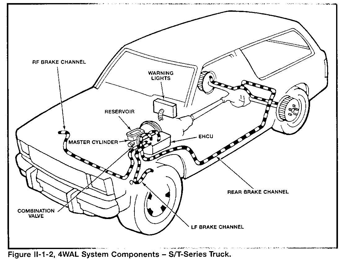
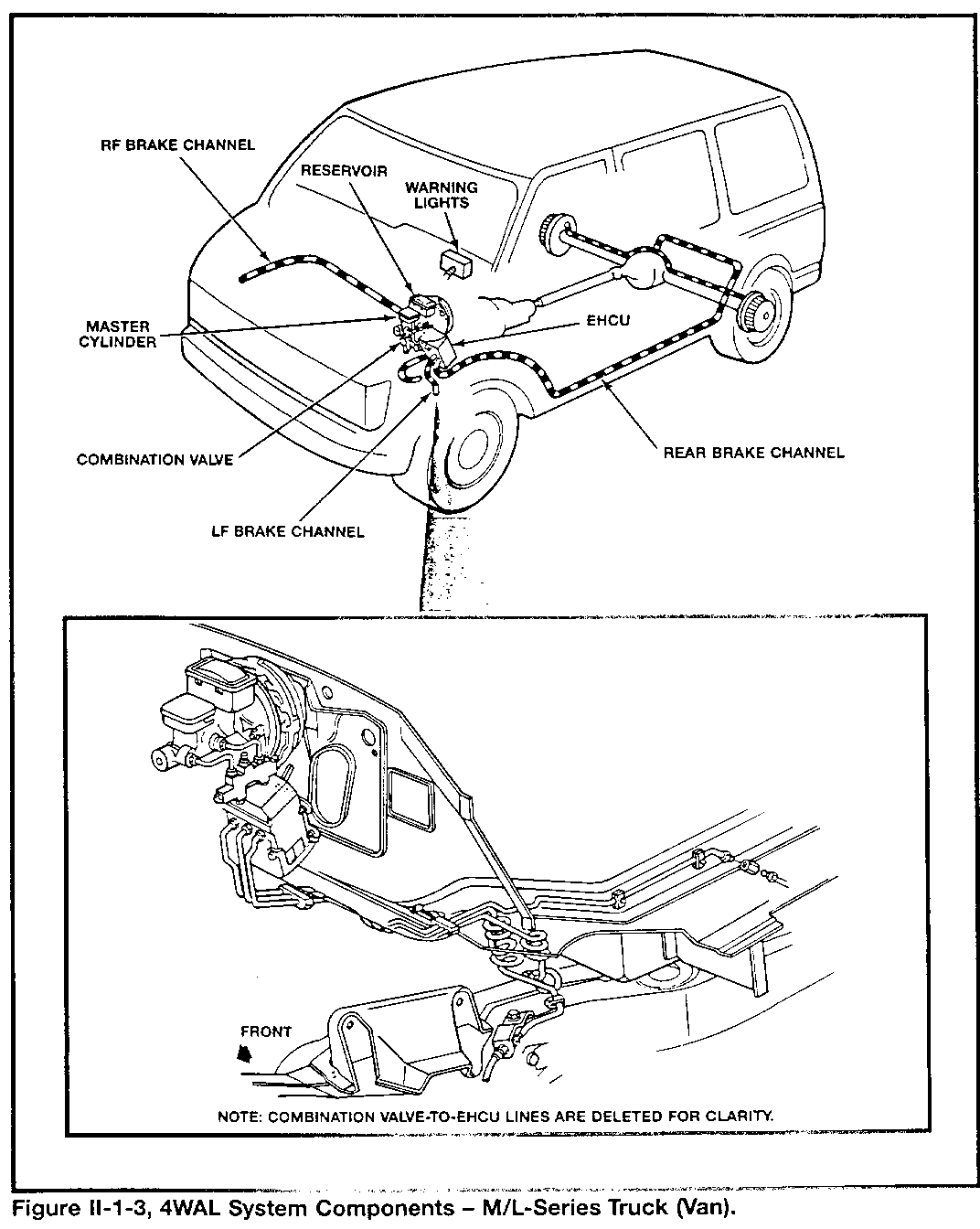
The 4WAL braking system has these groups of parts (refer to Figures II-1-2 and II-1-3):
Electro-Hydraulic Control Unit (EHCU), which includes:
- Electronic Control Unit (ECU) - Hydraulic control unit assembly - Pump motor and its relay-controlled circuit
Electrical connection to:
- Power circuits - "Brake" light circuit - Four Wheel Speed Sensors (LF, RF, LR, RR) - "Antilock" light circuit - Brake switch and "4WD" light circuits - Assembly Line Diagnostic Link (ALDL)
NOTE
The parts of the EHCU are serviced as one replacement EHCU assembly ONLY.
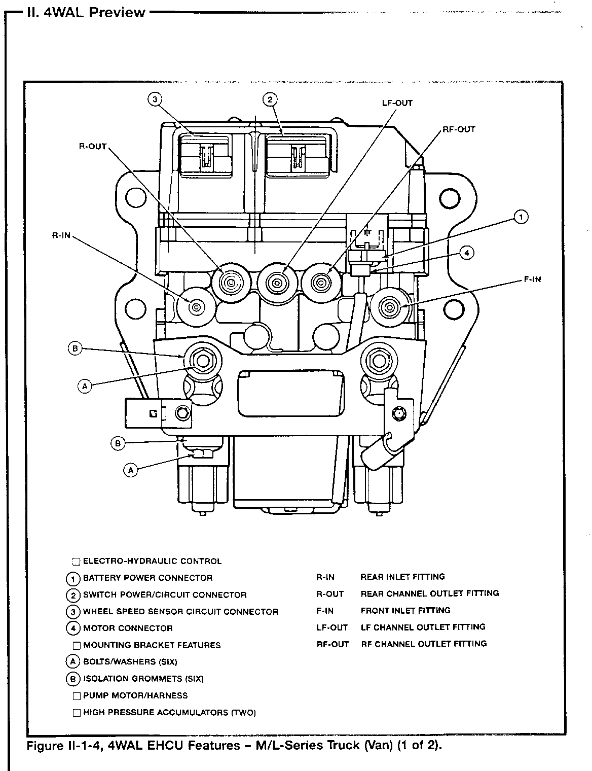
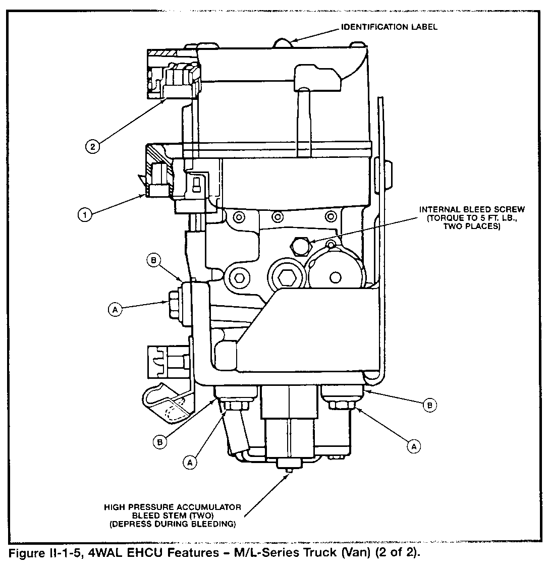
Refer to Figures II-1-4 and II-1-5 for EHCU feature information.
Overview of Operation
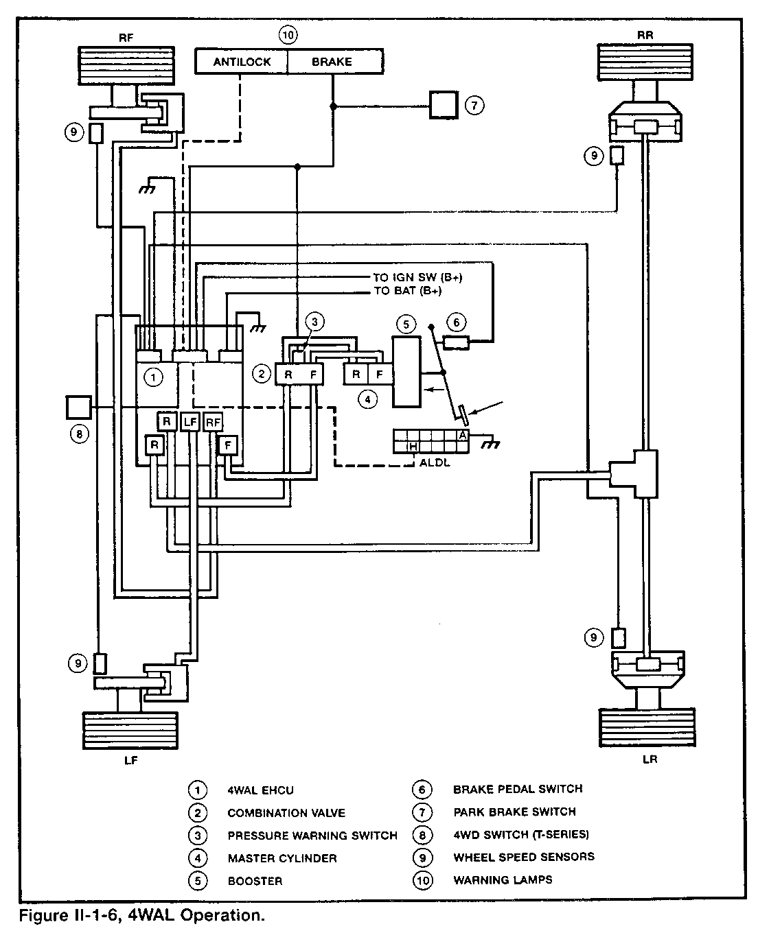
No Braking (refer to Figure II-1-6)
When the ignition switch is in the "run" position, the 4WAL ECU:
Performs a self check and external circuit checks. Will begin its operation. During initial vehicle movement, it performs an electro-hydraulic functional check, including pump, solenoids, and reset switches at 8 mph (once per ignition cycle).
NOTE
The 8 mph test will not occur until after the brake pedal is released, if a driver "rides" the pedal.
Non-Antilock Braking
When the driver applies the brake pedal:
The control unit assembly does not affect the front or rear hydraulic channels. The ECU prepares for possible antilock control by monitoring each of the four wheel speed sensor signals.
Antilock Braking
When the ECU sees that a wheel is ready to lock during braking, it:
Operates the control unit assembly solenoids for the LF, RF, or rear hydraulic channels. Each channel may be cycled independently through a pressure increase/maintain/decrease control sequence. Continues its control unit cycling as long as necessary during braking.
Diagnosis
When the ECU detects a system malfunction, it:
Disables antilock control. Completes the amber "Antilock" warning light circuit. Completes the red "Brake" warning light circuit if it detects a problem with the "Antilock" light circuit or the foundation brakes. Stores one or more trouble codes related to the detected problem. Displays the trouble code(s) by flashing the "Antilock" light when a technician makes a diagnostic request. Provides bi-directional data communication when a technician using the Tech 1 scan tool as part of system diagnosis.
II-2 Operation
Hydraulic Parts
The braking systems of the M/L- and S/T-Series trucks each have components that are matched to operate with specified maximum vehicle weights. The 4WAL hydraulic control unit assembly (part of the EHCU) is part of these specific hydraulic systems. During service, a technician must check that a specific 4WAL unit matches its application.
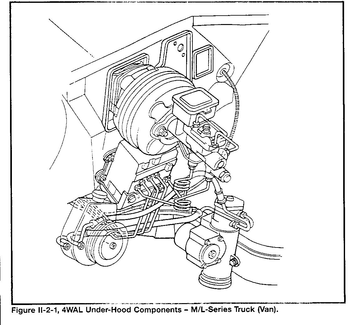
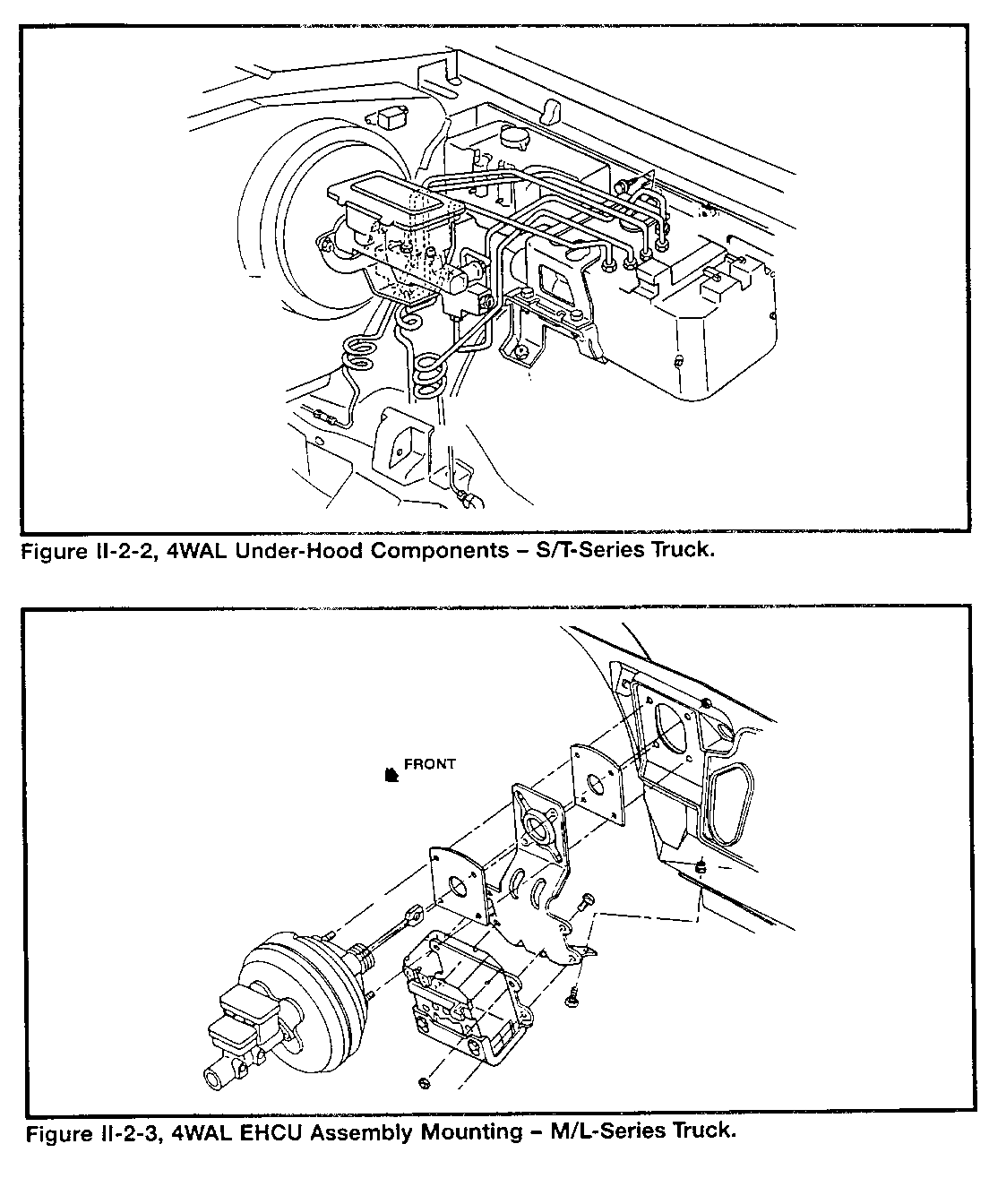
The EHCU mounts in the engine compartment, near the master cylinder (Figures 11-2-1 through 11-2-3). M/L-Series trucks use a booster-supported bracket (Figure 11-2-3) to hold the EHCU and its bracket in place. The S/7-Series trucks use a left inner fender bracket to support the EHCU/bracket assembly (Figure 11-2-2).
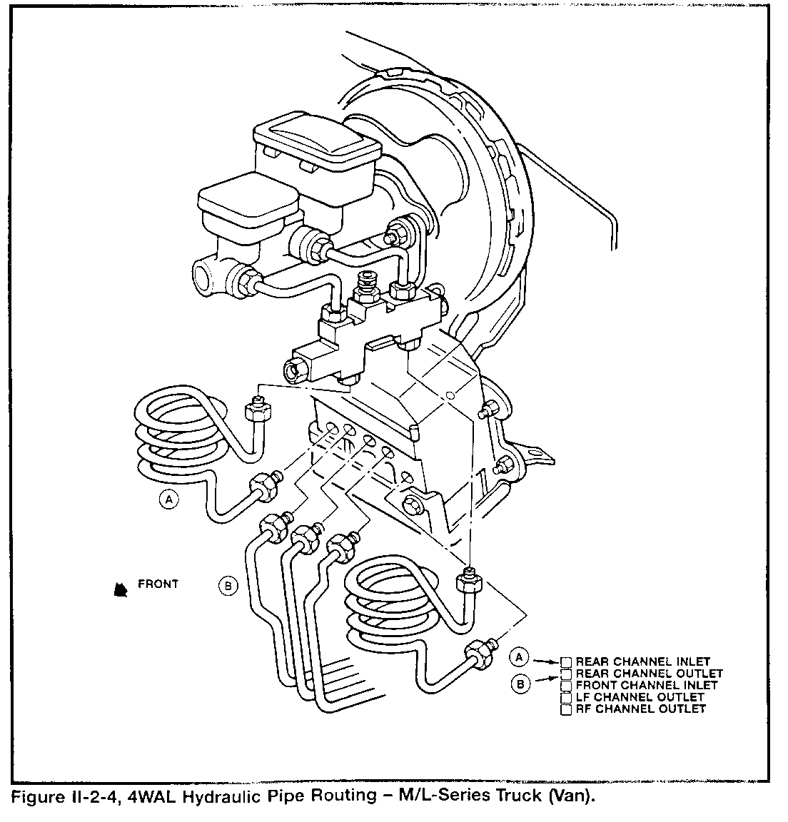
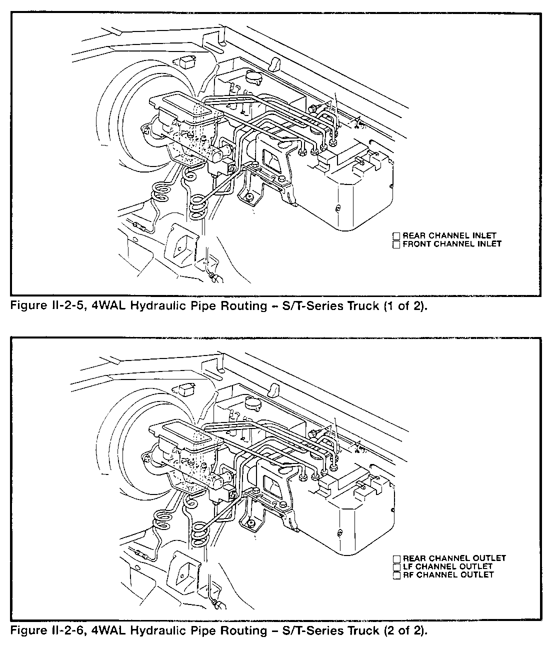
The braking systems used with 4WAL are of a LF/RF/rear split design. A combination valve connects the master cylinder to the front and rear channels. The 4WAL hydraulic control unit connects to the combination valve outlet fittings. Brake lines to the LF, RF, and rear channels connect to the hydraulic unit outlet fittings (Figures II-2-4, II-2-5, and II-2-6).
Electro-Hydraulic Parts
THE HYDRAULIC CONTROL UNIT
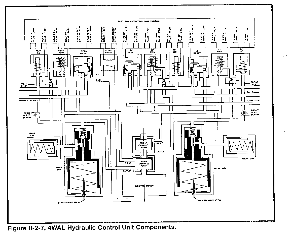
Using cycling action, the 4WAL system hydraulic control unit quickly changes the LF, RF, or rear channel hydraulic pressure during antilock braking. The control unit contains (Figure II-2-7):
A LF, RF, and rear isolation solenoid-operated valve (ISO) A LF, RF, and rear pulse-width modulation solenoid-operated valve (PWM) A check valve in the passage between each ISO and PWM valve A front and rear low-pressure accumulator (LPA) A front and rear high-pressure accumulator (HPA) A LF, RF, and rear reset switch A relay-operated electric motor that drives a front and rear channel pump Internal electrical connections to the ECU within the EHCU Service air bleed passages and valves for the accumulators
THE ISO VALVE
The ISO valve solenoid circuits involve internal connections to the ECU within the EHCU assembly. Each ISO valve is normally in an open position that allows fluid under pressure from the master cylinder/combination valve to move to the LF, RF, or rear channel.
When the ECU completes an ISO valve solenoid electrical circuit, the valve isolates master cylinder pressure from the wheel cylinder(s) (in the "pressure maintain" position) and prepares for antilock pressure control cycling to occur.
THE PWM VALVE
The PWM valve solenoid circuits also involve internal connections to the ECU within the EHCU assembly. Each PWM valve is normally in a position that allows fluid from the related ISO valve to move to the LF RF, or rear channel. At the same time, the valve blocks pressure in the pump inlet hydraulic circuit from affecting the ISO valve and wheel cylinder circuits.
When the ECU completes the solenoid circuit for a PWM valve, the valve works with the check valve and ISO valve to trap fluid under pressure. At the same time, the PWM valve connects the pump inlet circuit to the same channel, which results in wheel cylinder pressure decrease. After the ECU opens the PWM circuit, fluid under pump outlet pressure moves past the check ball and into the wheel cylinder circuit as pressure rises. The ECU controls each PWM valve by opening and closing its solenoid circuit a controlled amount of time (pulse-width modulation). The ECU will vary the "on" time (pressure decrease) and "off " time (pressure maintain) of the PWM valve while it keeps the ISO valve circuit complete.
THE LPA
Each LPA is a cylinder that contains a spring-loaded piston. During non-antilock braking, the LPA is empty. During antilock braking, the LPA receives fluid from the pump outlet that has entered the high pressure accumulator (HPA) and moved past the open bypass valve. The LPA also receives fluid from a wheel cylinder circuit when a PWM valve solenoid circuit is completed by the ECU.
THE HPA
The front and rear high pressure accumulators (HPA) are cylinders with spring-loaded pistons. Each piston has a bypass passage and valve that limit the HPA pressure from the pump outlet. As antilock braking control occurs, each channel pump moves fluid into its related HPA circuit. As this fluid under pressure pushes the HPA piston, the stem of the bypass valve bottoms in its bore. Further piston travel opens the bypass passage to the LPA and pump inlet. In this way, pump outlet fluid recirculates when it is not needed for antilock control action.
THE RESET SWITCH
The reset switch for each channel involves internal connection to the ECU bore and acts as an electrical contact. The bore has another contact at one end. A spring pushes the valve toward the contact until an antilock braking pressure decrease action occurs.
When an antilock pressure decrease action happens, unequal hydraulic pressure pushes the valve, opening an ECU logic circuit. This provides a feedback signal to the ECU regarding pressure changes as the result of control commands.
The reset switch also has a diagnostic function. During non-antilock braking, the pressures from both the master cylinder and wheel cylinder(s) affect the switch position. If a problem of unequal hydraulic pressure exists, the switch contacts will connect, alerting the ECU.
THE PUMP
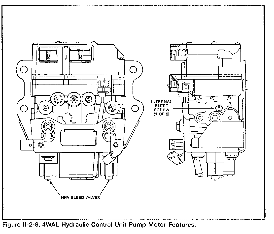
See Figure II-2-8 ...
During antilock braking control, the ECU operates the electric motor that drives the pump for each channel. The ECU uses a relay within the EHCU to complete the pump motor circuit. A fusible link-protected feed wire and ground wire provide a power supply circuit for the pump motor which is external of the ECU. The pumps provide fluid movement under high pressure for the two HPA circuits. They also create the low pressure needed for LPA circuit operation.
SERVICE BLEED VALVES
The hydraulic control unit provides two internal air bleed screws and two HPA air bleed valve stems that a service technician uses to purge the accumulators.
Summary of Hydraulic Control Unit Operation
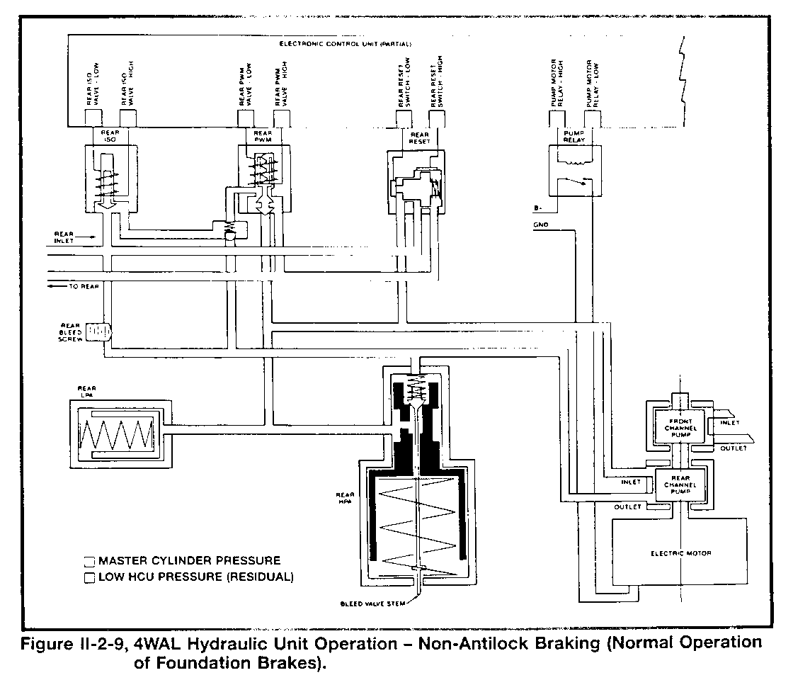
During NON-ANTILOCK BRAKING, the parts of the hydraulic control unit work as follows (Figure II-2-9).
Fluid under pressure from the master cylinder moves through the ISO valve (solenoid de-energized) for each of the channels to the PWM valve. Each PWM valve allows the fluid from an ISO valve to move to the outlet fitting for its related channel under master cylinder pressure (solenoid de-energized). The ECU does not complete the relay coil part of the pump motor circuit and it does not operate the two pumps. The front and rear LPA circuits have residual pressure. The front and rear HPA circuits have residual pressure. The reset valve for each channel does not move because the difference in pressures is not great enough.
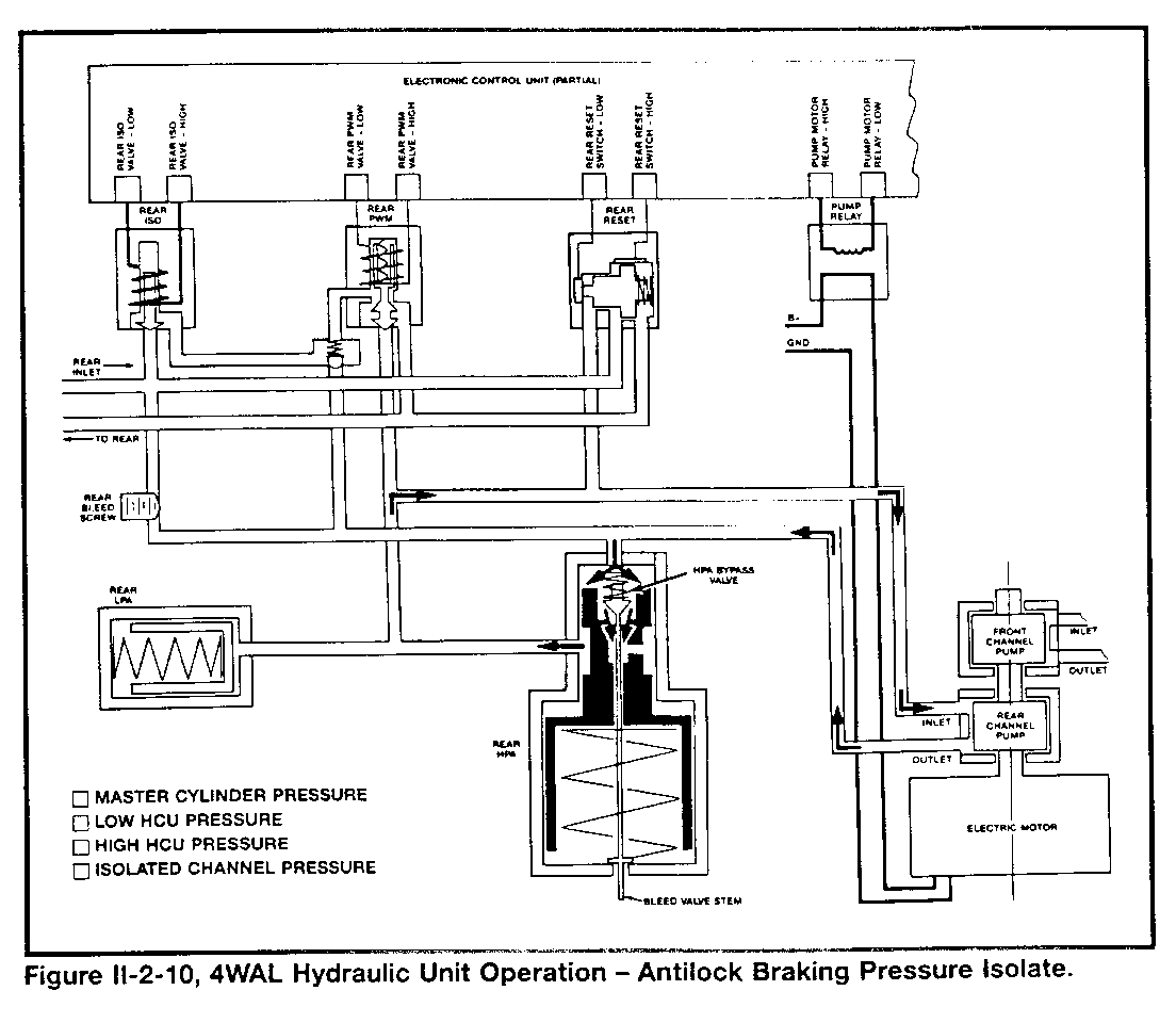
During the PRESSURE ISOLATE part of antilock braking, the parts of the hydraulic control unit work as follows (Figure II-2-10, LF channels):
Fluid under pressure from the master cylinder valve stops at the ISO valve (solenoid energized) for the channel being controlled. Each PWM valve (solenoid de-energized) allows the pressure of the fluid in the wheel cylinder part of the channel to be maintained. The ECU completes the relay coil part of the pump motor circuit and the motor armature operates both of the channel pumps. The front and rear LPA circuits have low pressure, provide pump inlet fluid, and are prepared for antilock braking. The front and rear HPA circuits have high pressure and are prepared for antilock braking (the HPA bypass valves may be open). The reset valve for the channel does not move because the difference in pressures is not great enough.
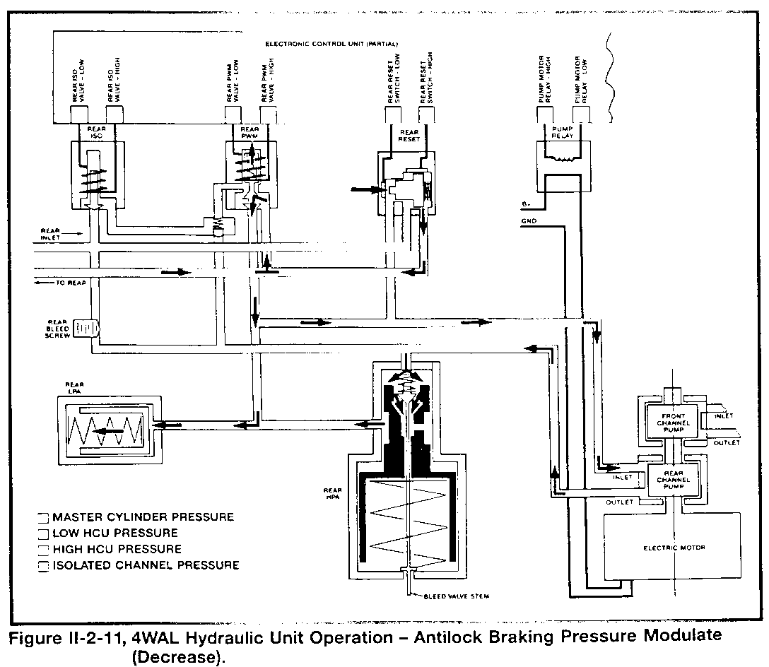
During the PRESSURE MODULATE-DECREASE part of antilock braking, the parts of the hydraulic control unit work as follows (Figure II-2-11, LF channel):
- Fluid under pressure from the master cylinder stops at the ISO valve (solenoid energized).
- The ECU completes the PWM valve solenoid circuit, and the pump inlet/LPA hydraulic circuit connects to the wheel cylinder part of the channel (this results in a channel pressure decrease action).
- The ECU continues to complete the relay coil part of the pump motor circuit and operates the two channel pumps.
- The front and rear LPA circuits have low pressure, provide pump inlet fluid, and are prepared for antilock braking (the LPA related to the channel being controlled receives fluid under pressure during decrease action).
- The front and rear HPA circuits continue to have high pressure and are prepared for additional antilock braking action (the HPA bypass valves may be open).
- The reset valve for the channel being controlled may move if the difference in pressures is great enough.
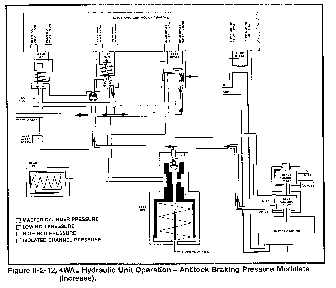
During the PRESSURE MODULATE-INCREASE part of antilock braking, the parts of the hydraulic control unit work as follows (Figure II-2-12, LF channel):
- Fluid under pressure from the master cylinder stops at the ISO valve (solenoid energized).
- The ECU opens the PWM valve solenoid circuit, and the pump outlet/HPA hydraulic circuit connects to the wheel cylinder part of the channel until pressure is stable (this results in a channel pressure increase action).
- The ECU continues to complete the relay coil part of the pump motor circuit and operates the two channel pumps.
- The front and rear LPA circuits have low pressure, provide pump inlet fluid, and are prepared for antilock braking.
- The front and rear HPA circuits continue to have high pressure and are prepared for additional antilock braking action (the HPA for the channel being controlled will have a momentary drop in pressure during increase action).
- The reset valve for the channel being controlled moves to its original position as pressures balance.
Electrical Parts
THE ECU AND ITS CIRCUITS
The 4WAL Electronic Control Unit has a microprocessor and circuits that:
- Monitor the brake switch input that tells it whether or not to prepare for possible antilock braking control.
- Operate the integral control unit assembly during antilock braking based on comparing the four wheel speed sensor signals to its own program stored in memory.
- Detect 4WAL system-related problems and take diagnostic action.
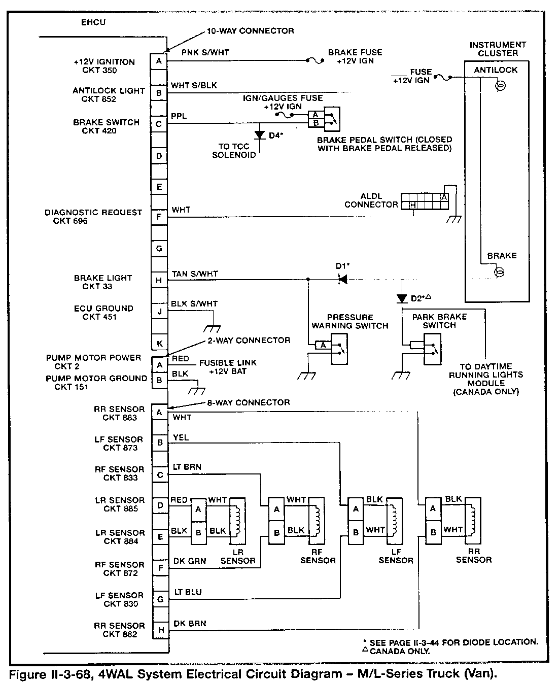
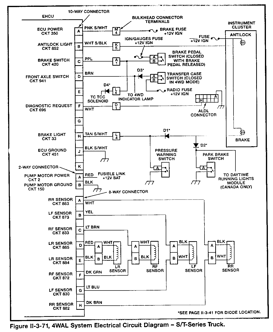
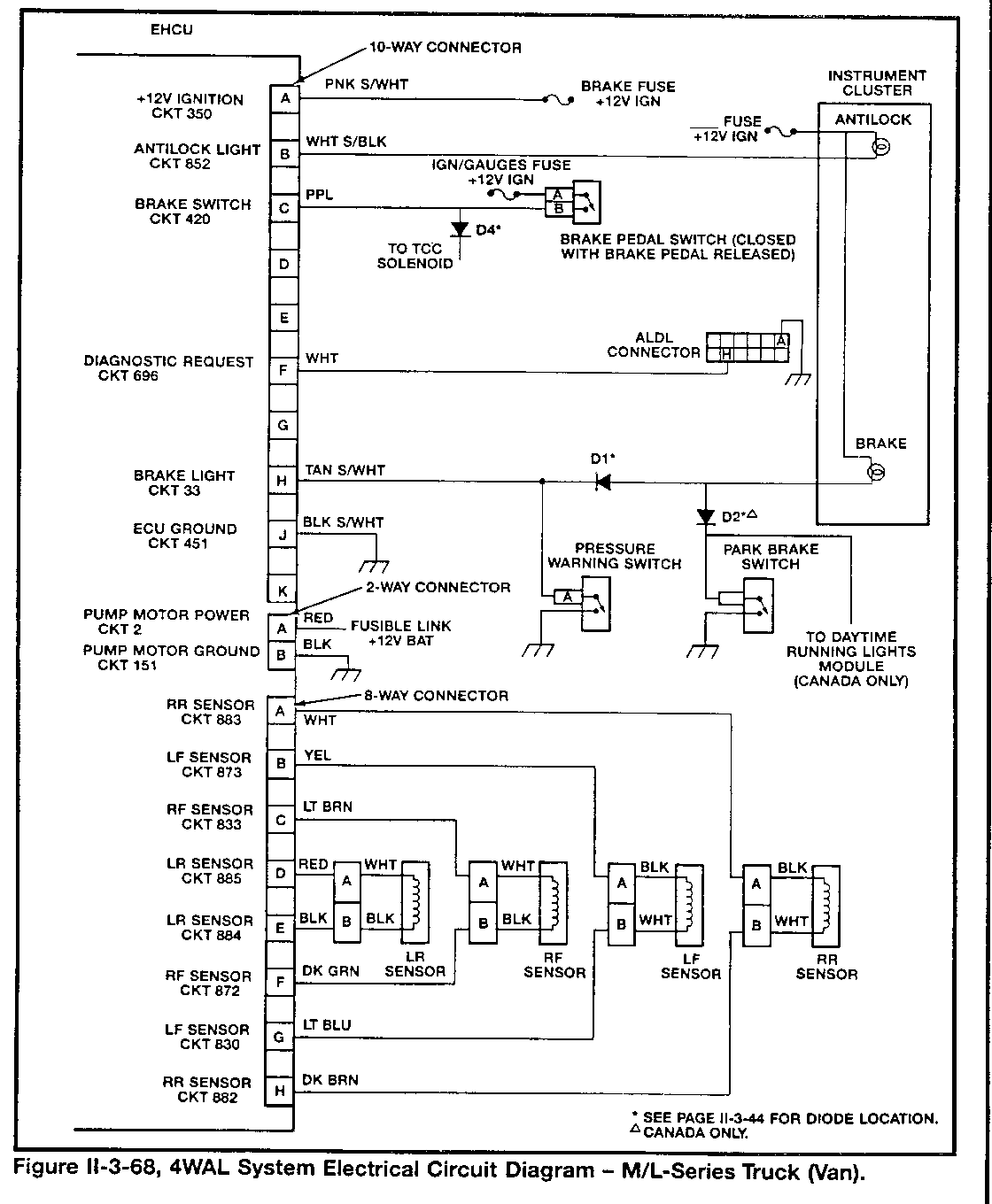
Refer to the fold-out electrical diagrams (Figures II-3-68 and II-3-71) for details about the ECU and its circuits.
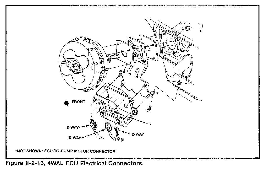
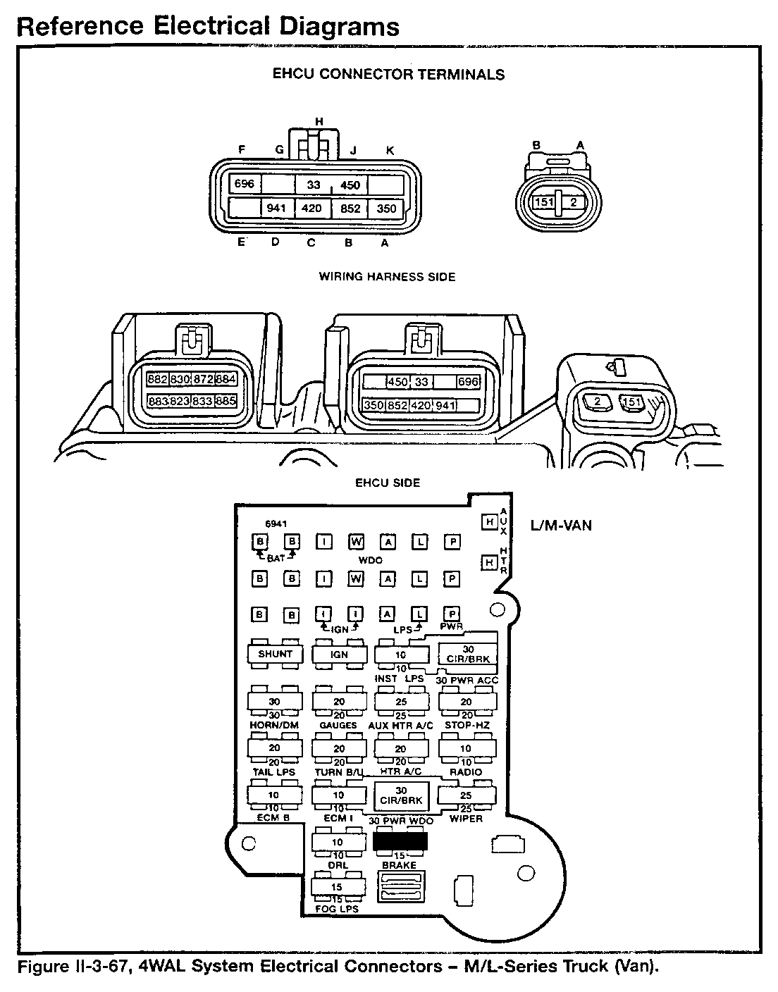
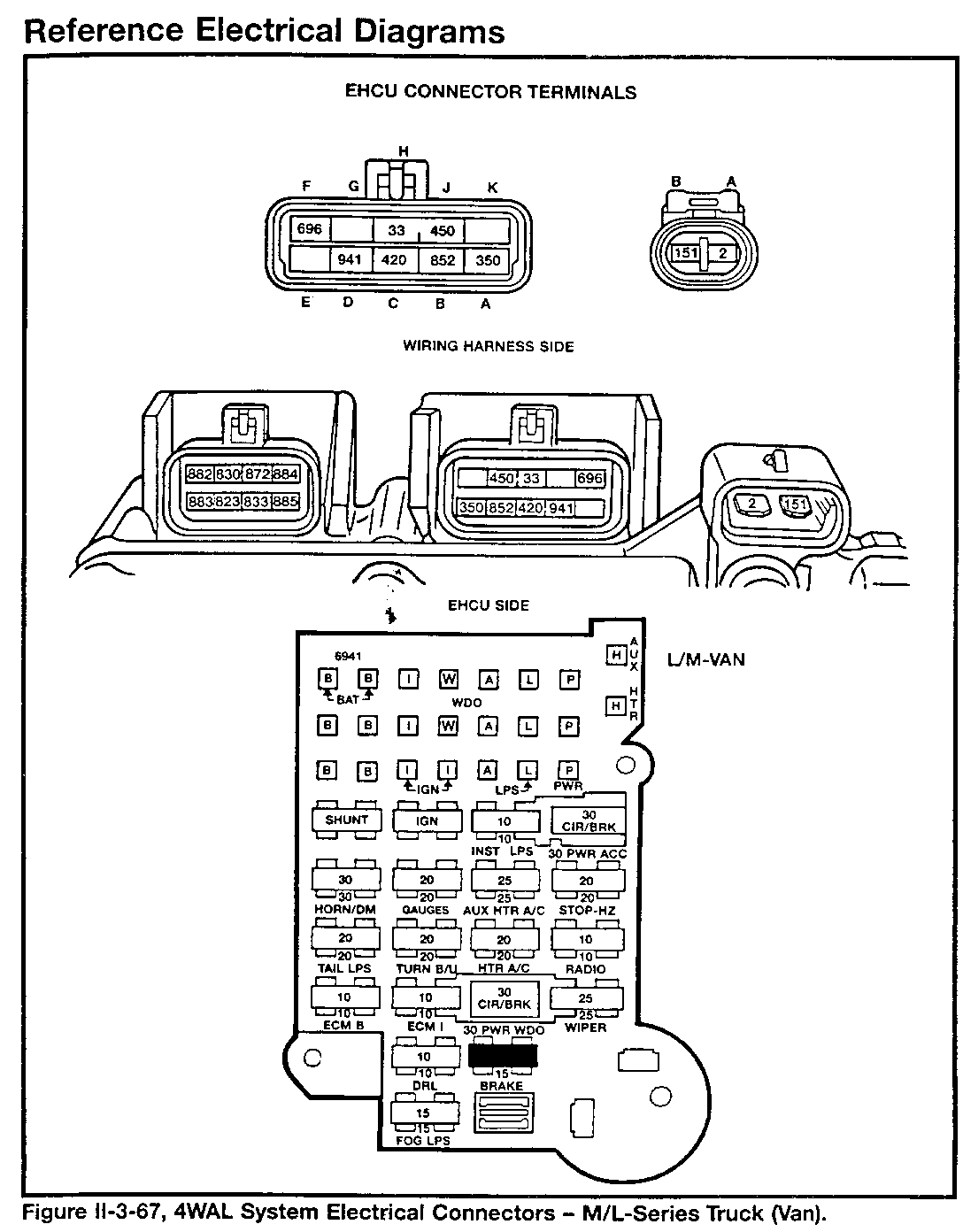
The ECU has four electrical connectors (Figure II-2-13):
- A two-way, with B+ and ground wire terminals for power supply
- An eight-way (with terminals A through H), that connects it to the wheel speed sensors
- A ten-way (with terminals A through K), that connects it to the rest of the vehicle's electrical circuits
- A two-way, with B+ and ground wire terminals for the pump motor
The ECU has an operating power circuit (ten-way connector terminals A and J), that has ignition switch control and fuse protection.
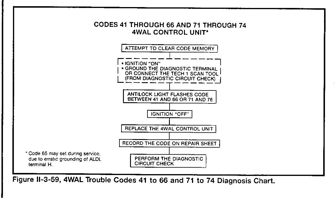
The ECU will disable antilock control, complete the "Antilock" light circuit, and store trouble codes if it detects one of the following problems with itself:
- Random-Access Memory (RAM) error (Code 71)
- Read-Only Memory (ROM) error (Code 72)
- Internal circuit error (Code 73)
- Internal circuit error causing excessive isolation time (Code 74)
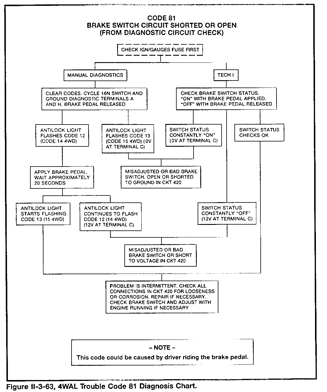
THE BRAKE SWITCH CIRCUIT
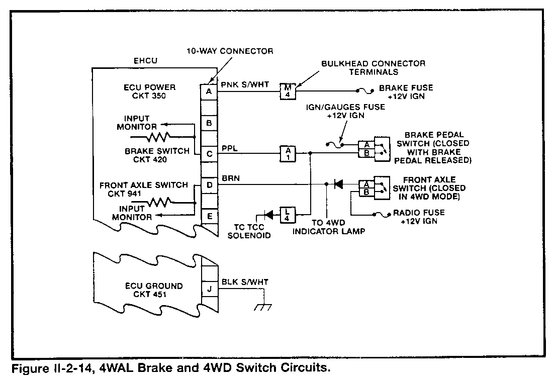
The 4WAL system uses an input signal circuit to the ECU from a brake pedal-activated switch circuit (Figure II-2-14).
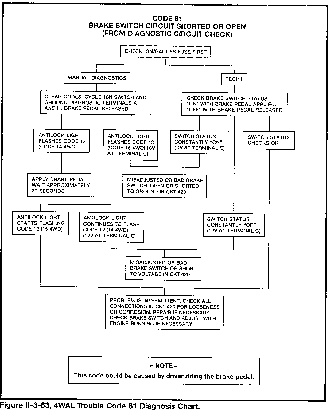
When the driver applies the brake pedal, the circuit voltage at ECU terminal C is less than 1 volt. A released brake pedal will close the switch contacts, providing 12 volts at terminal C. These signals tell the ECU:
Not to prepare for possible antilock braking (12 volts).
To get ready for control valve operation during antilock braking (low voltage).
The brake switch contacts also control power to the TCC solenoid on vehicles equipped with automatic transmissions.
The ECU will disable antilock control, complete the "Antilock" light circuit, and store a trouble code if it detects a continuous low-voltage brake switch input (brakes applied signal) when the ignition switch has been turned to "run," and the vehicle is moving at a speed above 35 mph for ten seconds. This indicates that the brake switch circuit is open continuously (Code 81).
THE 4WD SWITCH
The T-Series truck has a switch mounted to the front axle which is open in 2WD mode and closed in 4WD mode. This switch is part of an indicator light circuit and is mechanically operated by the movement of shift mechanism linkage within the transfer case.
The ECU will change its antilock braking program when it sees a signal (12 volts) that the front axle is in 4WD mode. The signal is less than 1 volt when the contacts of the switch are open. The ECU does not monitor the 4WD switch circuit for problems.
WHEEL SPEED SENSORS
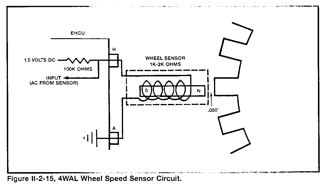
The 4WAL system uses four individual wheel speed sensor circuits to send input signals to the ECU. Each sensor has (Figure II-2-15):
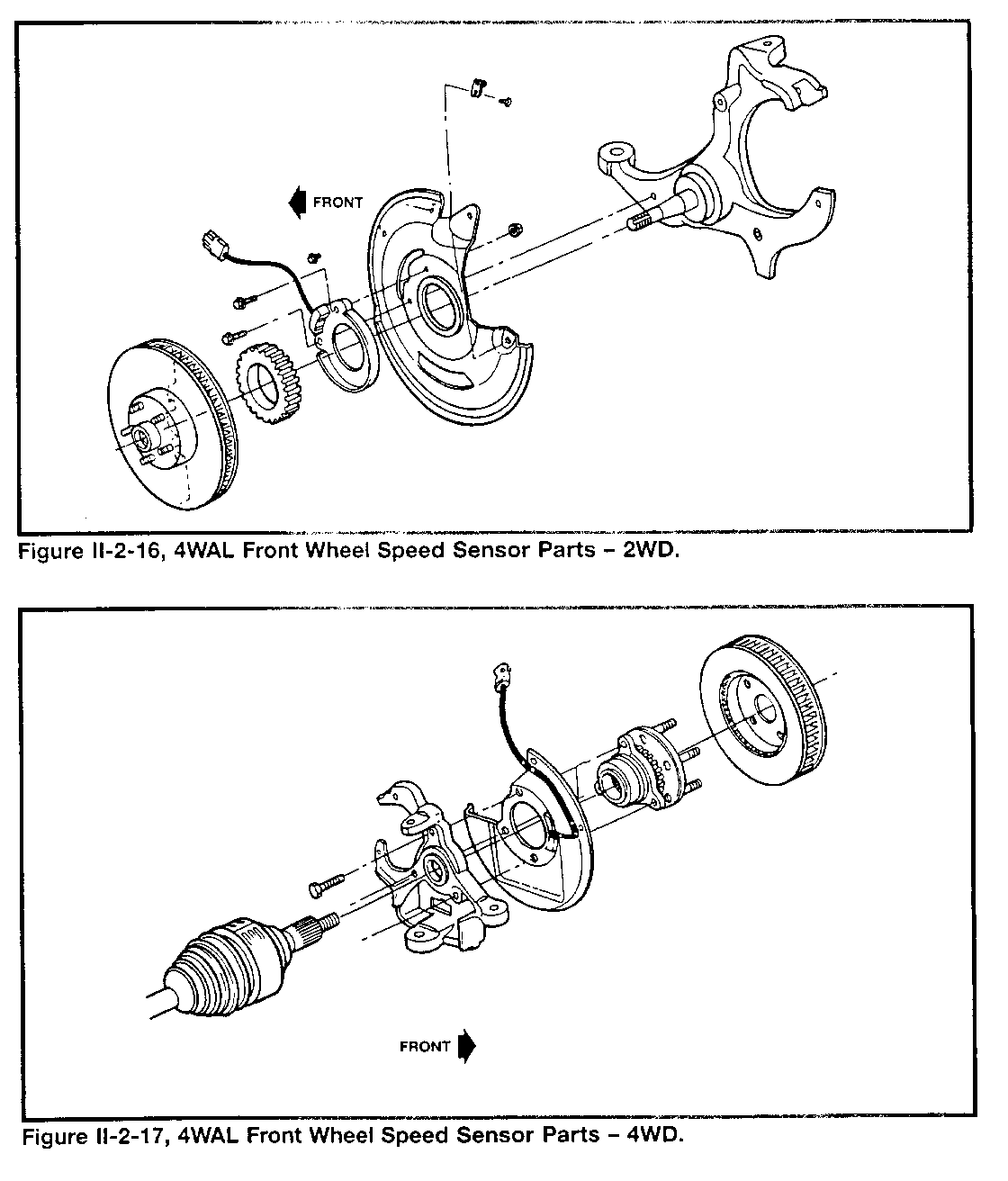
- A metal ring (called a "tone ring" or "sensor ring") with teeth on its outside diameter, that is fastened to the:
- Inside hub surface of front brake discs for 2WD vehicles
- Front wheel hub/bearing assembly for 4WD vehicles
- Rear axle shaft for both 2WD and 4WD vehicles
- A magnet/coil pickup that mounts to the:
- Front steering knuckle/splash shield
- Rear axle housing flange/backing plate
- An air gap between the toothed ring and the magnet/coil, that is approximately 1.27 mm (0.050 in.) and is not adjustable
When each tooth of the ring gets closer to the magnet/coil, the lines of magnetic force around the magnet move as they become stronger. This movement generates a small electrical signal traveling between the coil and the ECU in a certain direction.
When each tooth of the ring aligns with the magnet/coil, the lines of magnetic force around the magnet stop moving. This is because the magnet is as strong as possible. This stops the small electrical signal between the sensor coil and the ECU.
When each tooth of the ring moves away from the magnet/coil, the lines of magnetic force around the magnet move as they become weaker. This movement generates a small electrical signal traveling between the coil and the ECU in a direction opposite to the previous signal. When the tooth moves a certain distance away from the magnet/coil, the electrical signal stops.
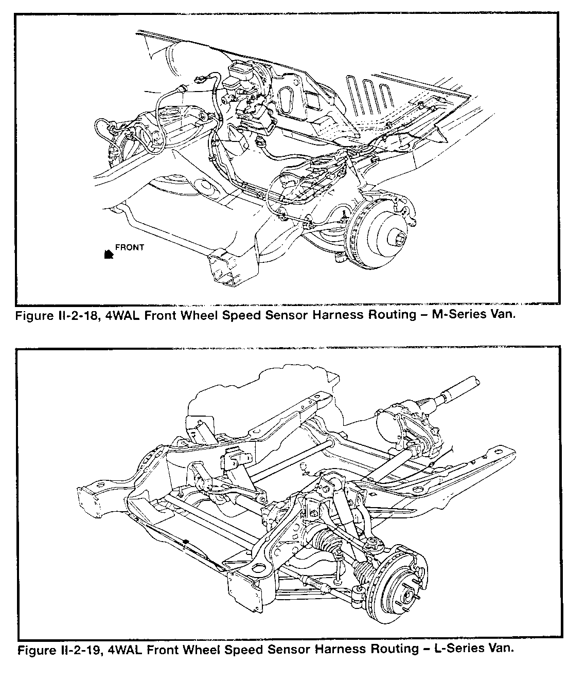
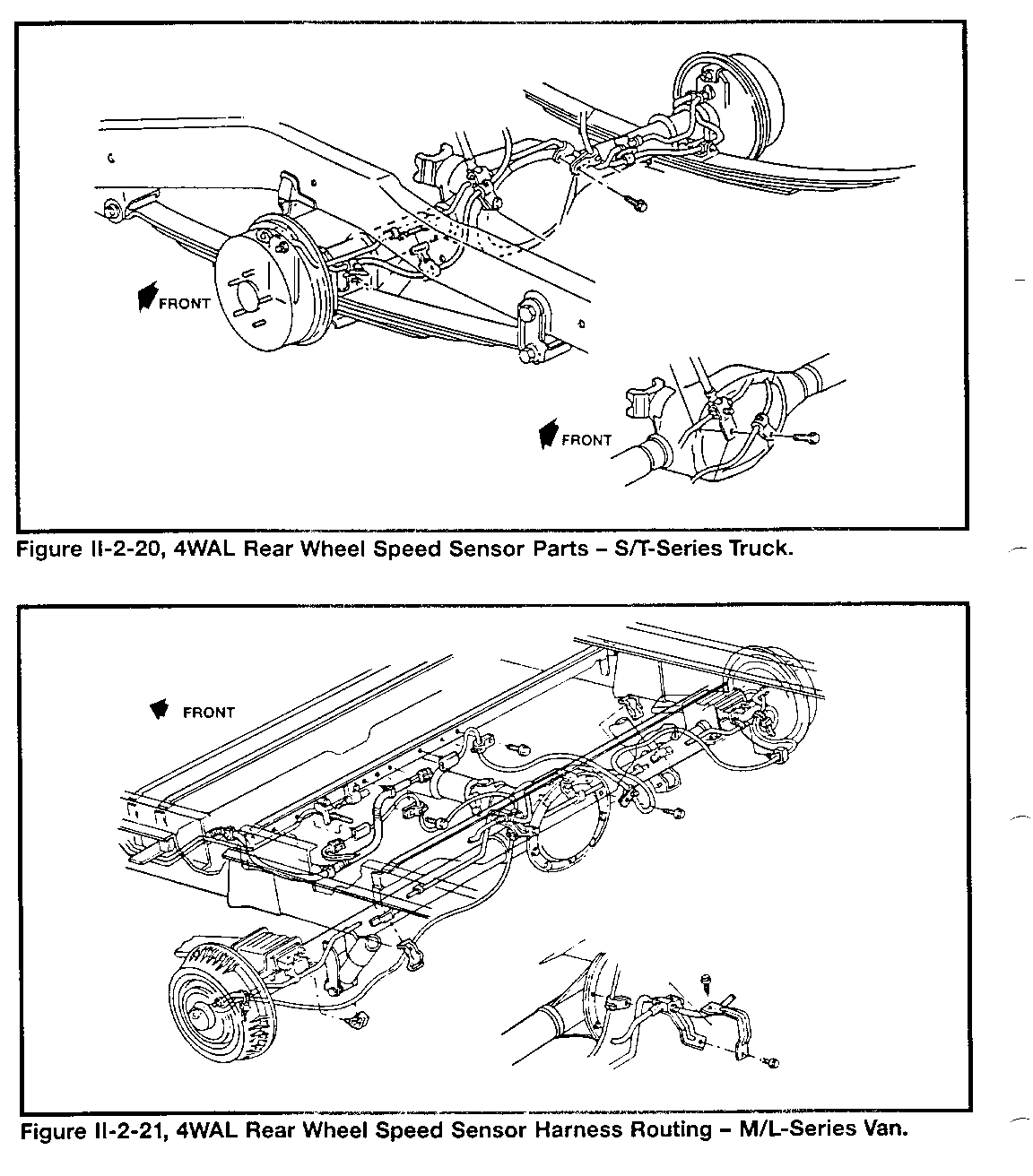
As the next tooth of the ring comes closer to the magnet/coil, the process of generating an alternating current (AC) signal begins again. The ECU compares the four separate AC signals and can detect braking deceleration from other vehicle maneuvers that cause individual wheel speed changes. Refer to Figures II-2-16 to II-2-21 for wheel speed sensor construction details.
The sensor-to-ECU wiring includes a special harness with four two-way connectors. The routing of the harness is carefully positioned to prevent damage from the wheels, brake/suspension parts, and drivetrain components.
- NOTE -
Exercise care in routing the wheel speed sensor wires. Misrouting may cause Electromagnetic Interference (EMI) faults.
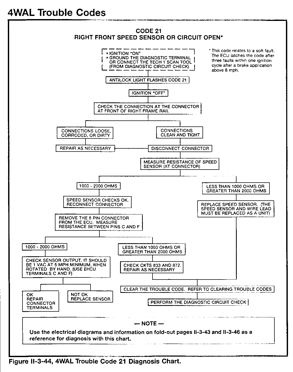
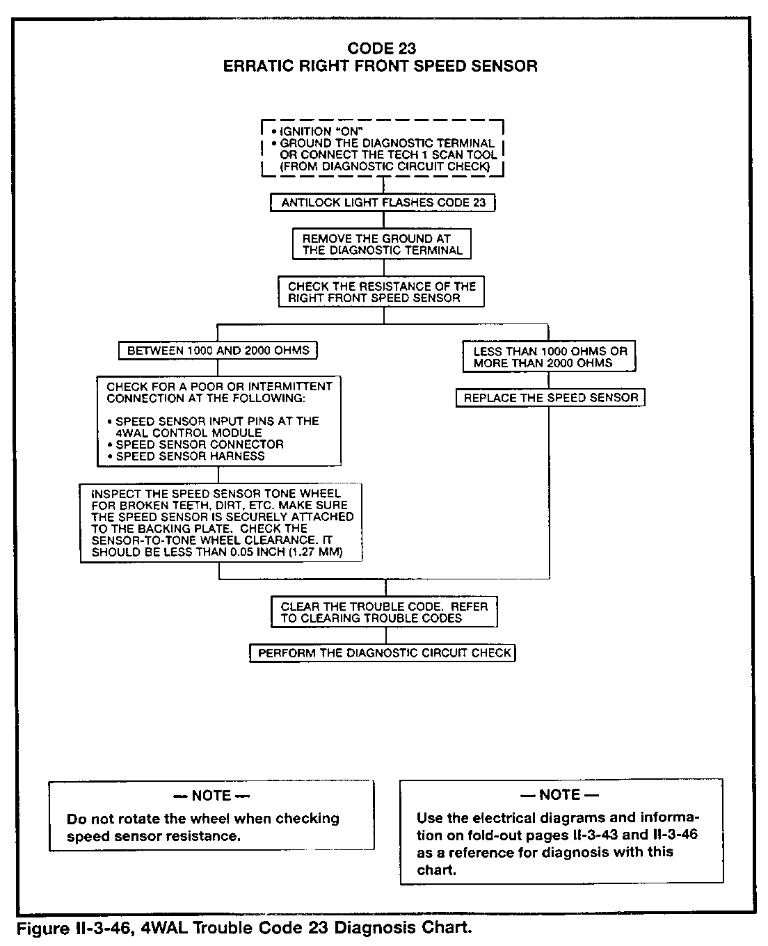
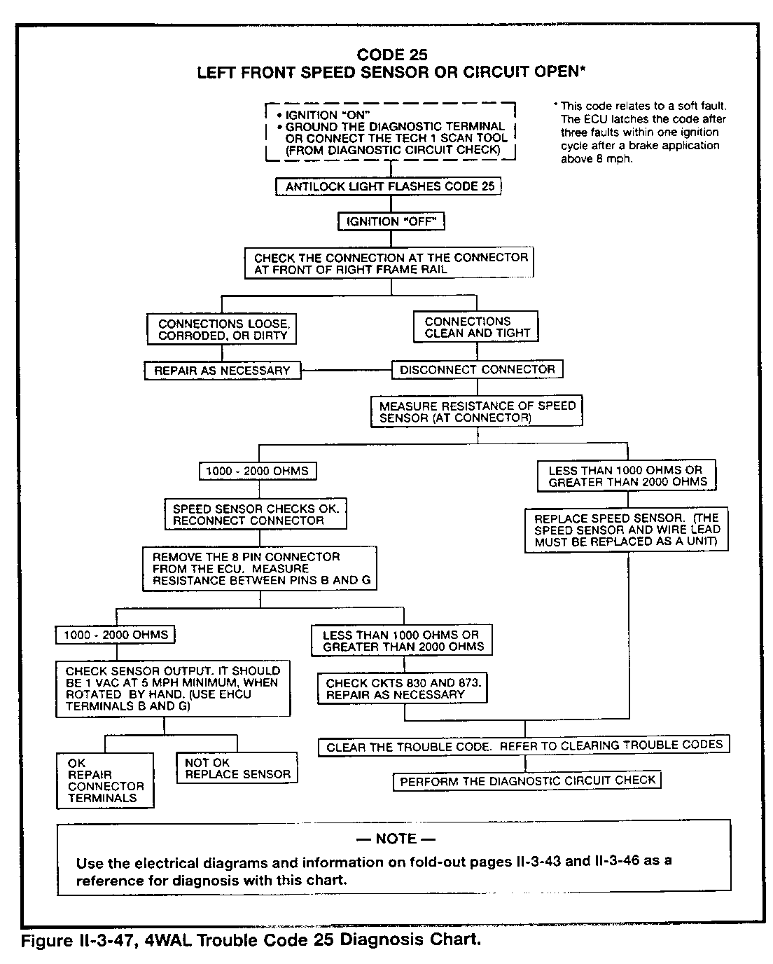
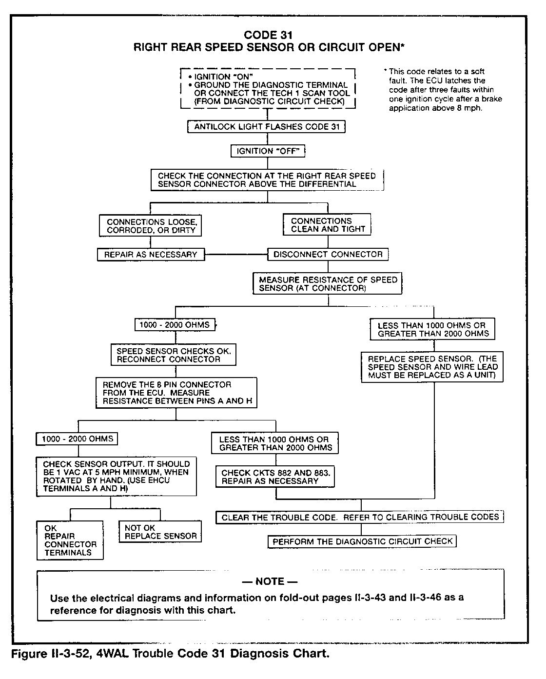
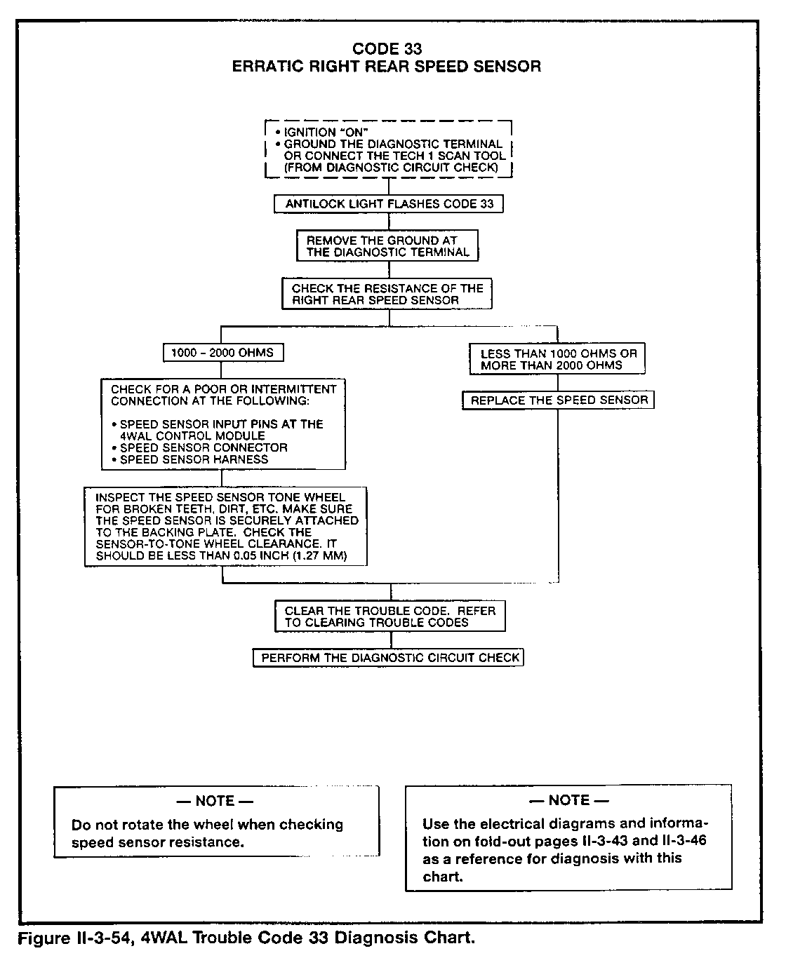
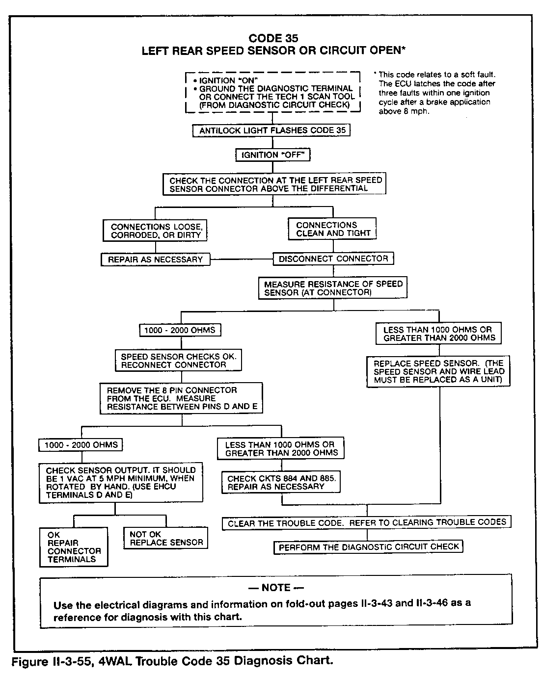
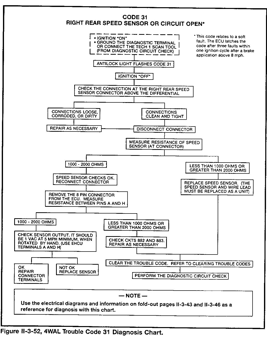
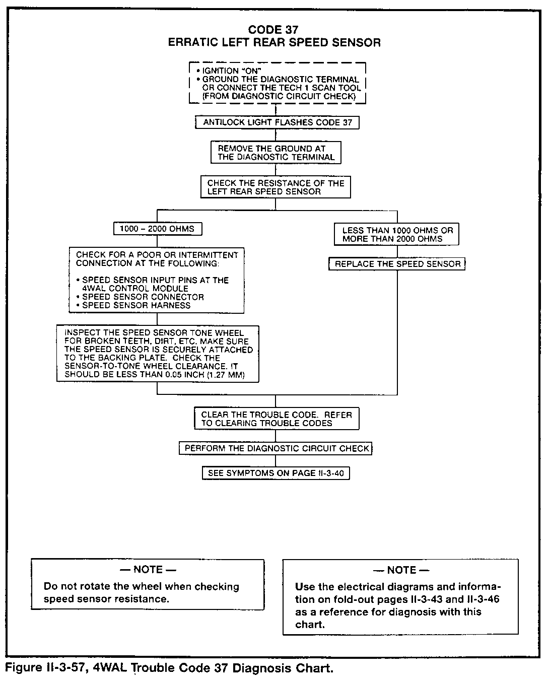
Each wheel speed sensor generates an alternating current (AC) signal in its coil. Each sensor circuit has 1000- to 2000-ohm resistance.
The ECU will disable antilock control, complete the "Antilock" light circuit, and store trouble codes if it detects the following problems with any or all of the wheel speed sensors:
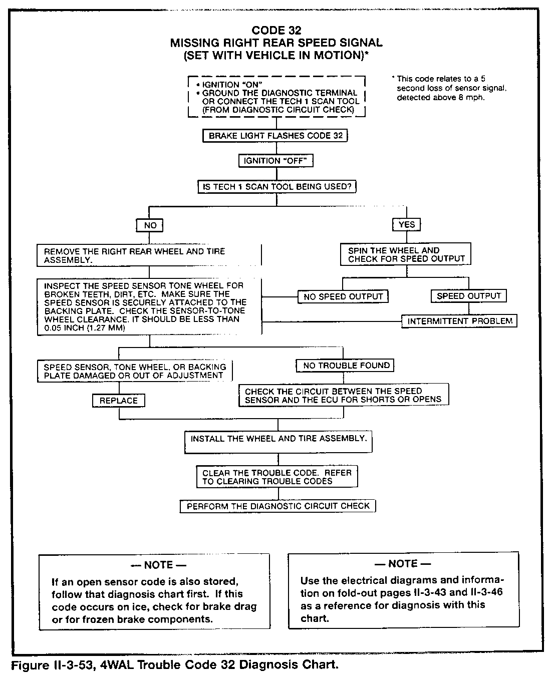
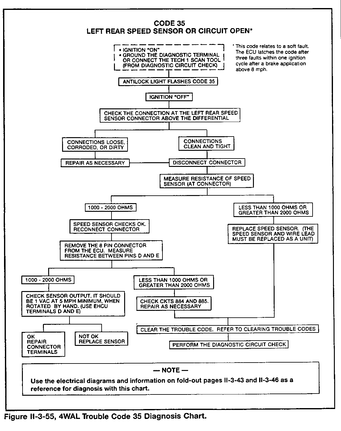
Incorrect circuit resistance when checked with no vehicle movement (the ECU will "latch" these codes after the first brake application above 8 mph):
- Code 21 for RF - Code 31 for RR - Code 25 for LF - Code 35 for LR
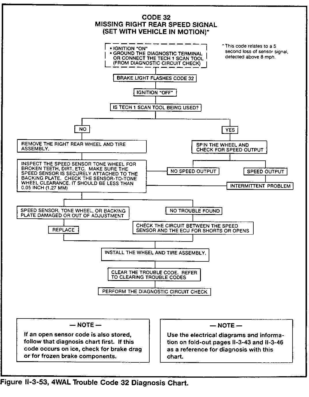
Incorrect sensor voltage output during vehicle movement (the ECU detects no signal when vehicle speed is above 8 mph):
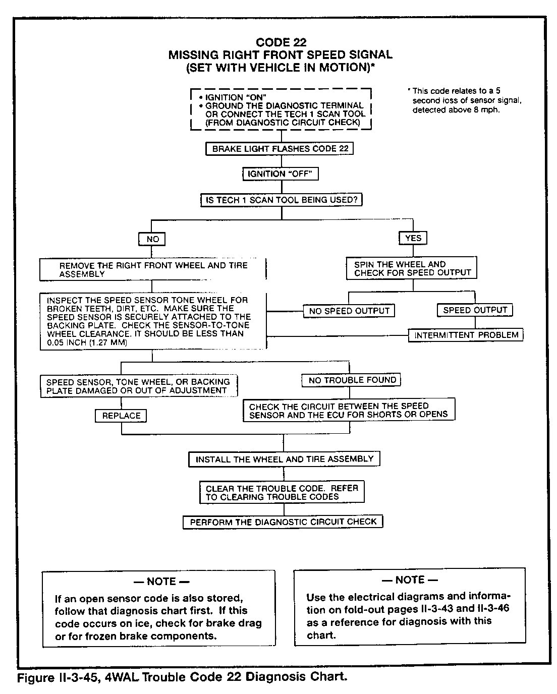
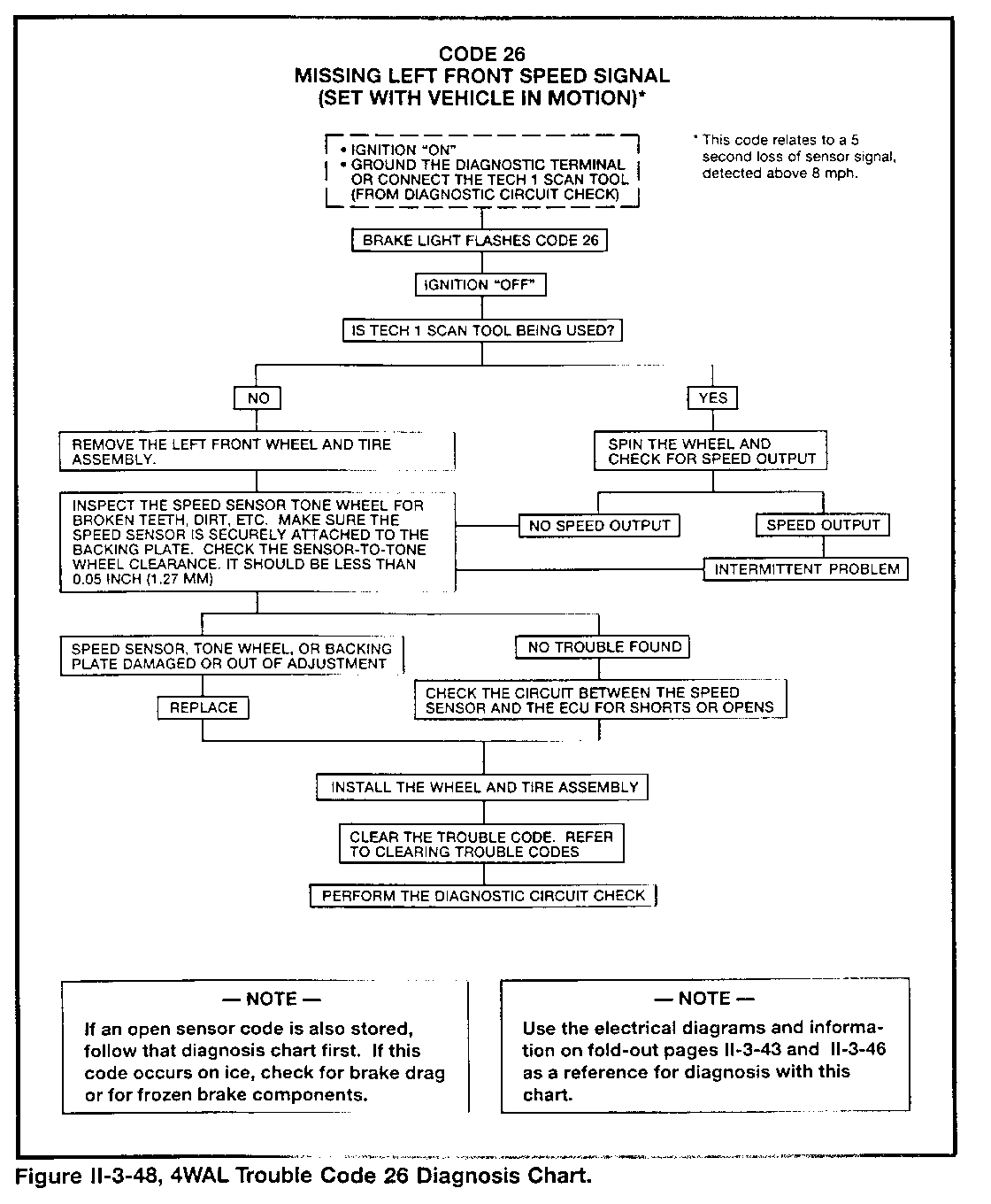
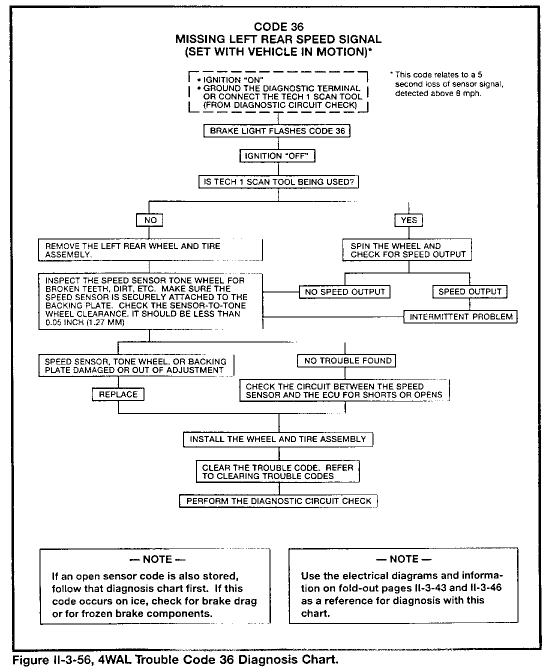
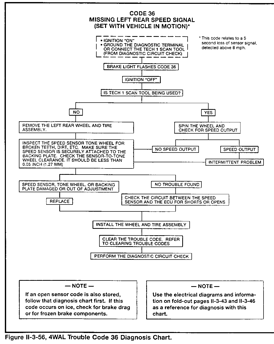
- Code 22 for RF - Code 32 for RR - Code 26 for LF - Code 36 for LR
NOTE
The ECU will disable antilock control and complete the "Antilock" light circuit for detected problems related to the above codes ONLY during the time it sees a fault present. However, the ECU will store a code in memory if additional conditions are met.
Erratic sensor voltage output during vehicle movement:
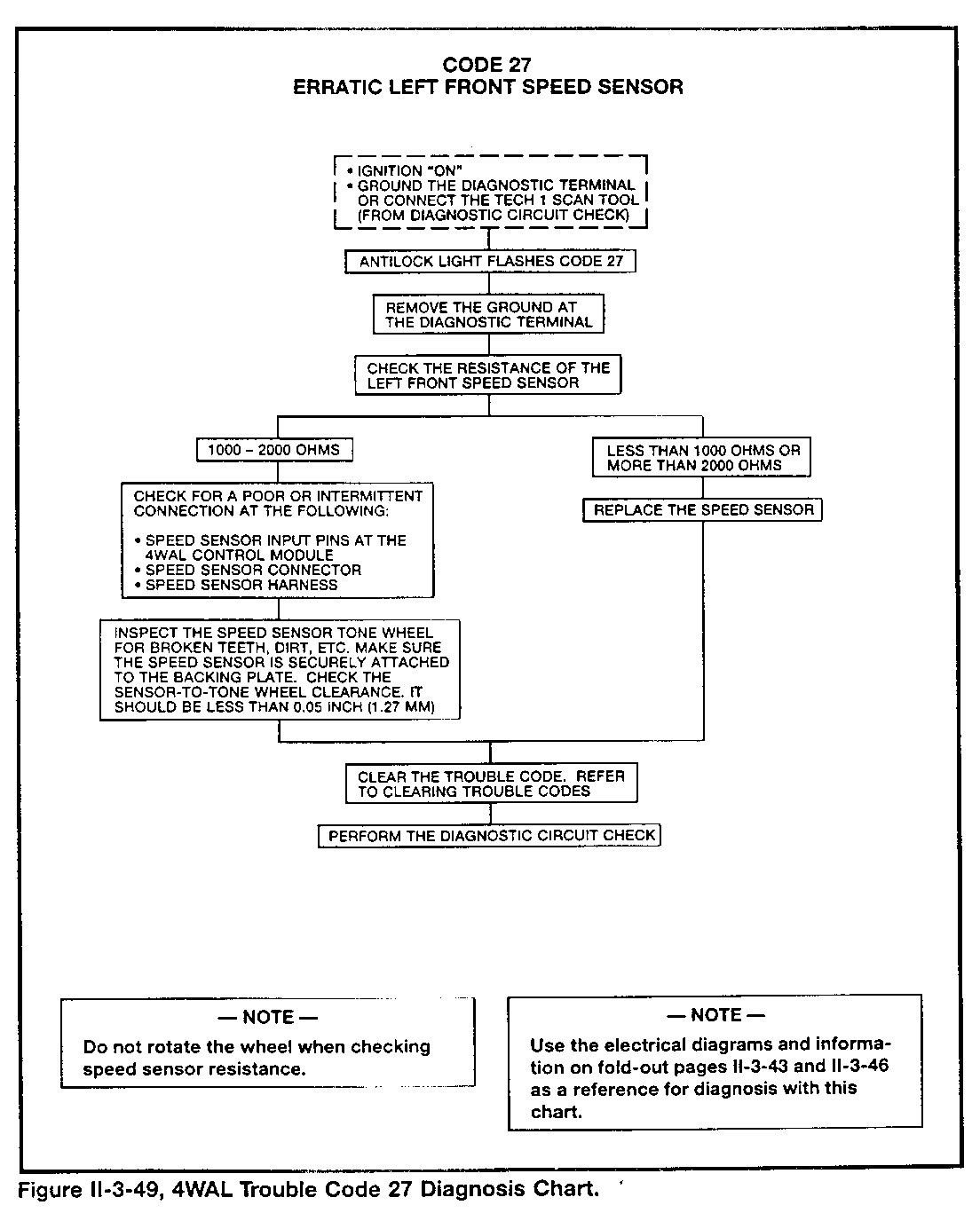
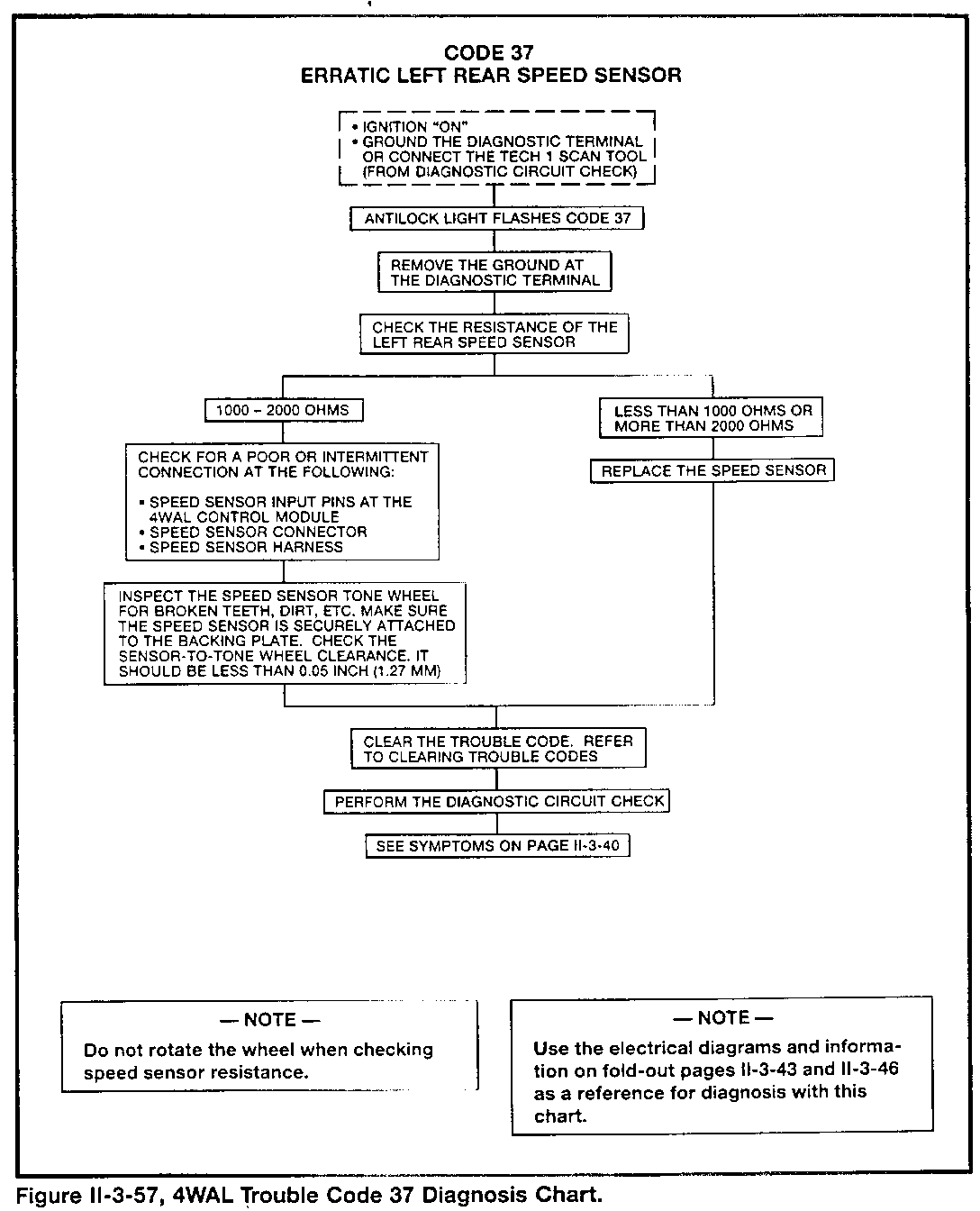
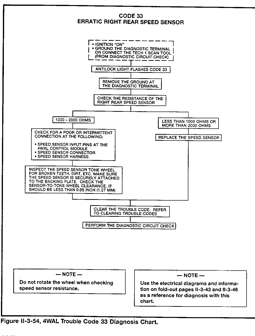
- Code 23 for RF - Code 33 for RR - Code 27 for LF - Code 37 for LR
NOTE
The ECU will disable antilock control and complete the "Antilock" light circuit for detected problems related to the above codes during the time it sees a fault present AND until its memory is cleared by a technician.
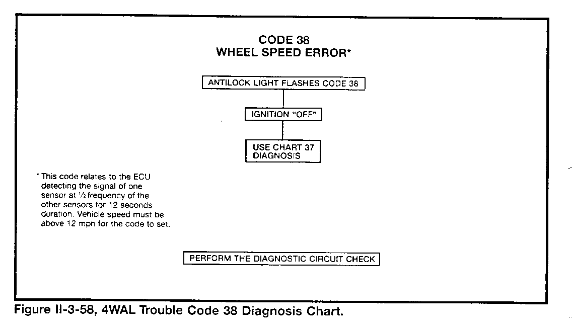
Three additional codes exist for wheel speed sensor faults:
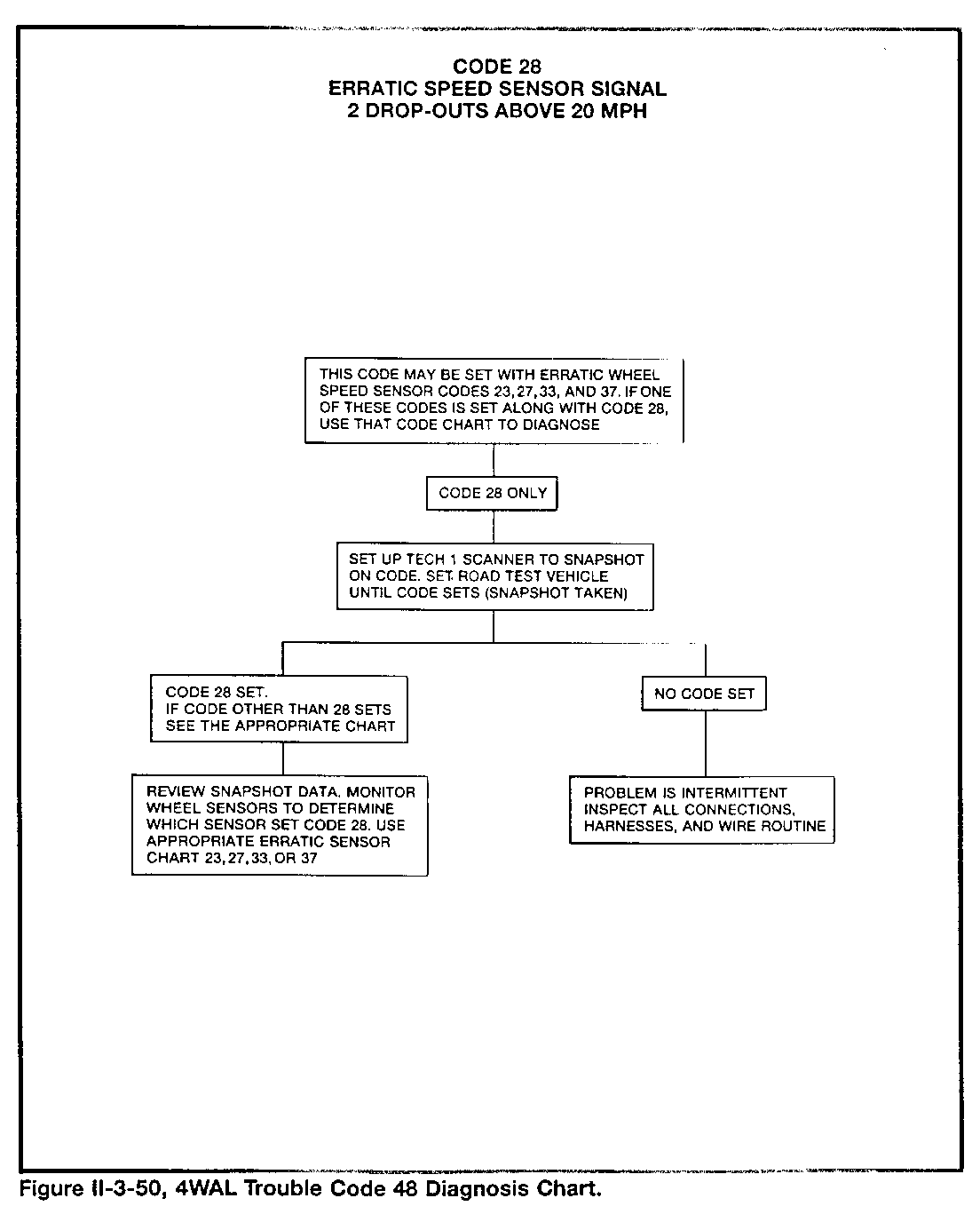
- Code 28 - One to two signal "drop-outs" above 20 mph
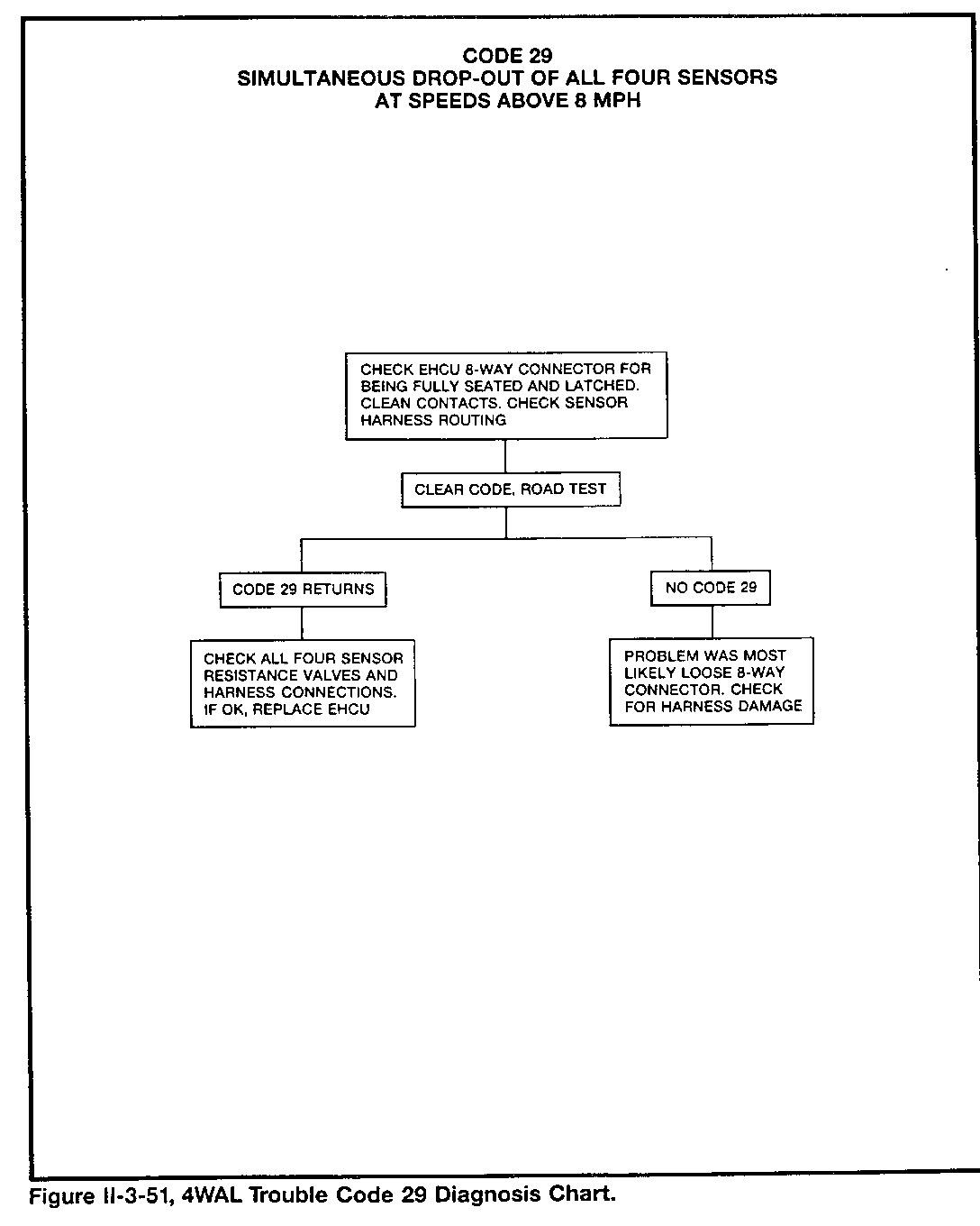
- Code 29 - All four sensor signals "drop-out" at the same time
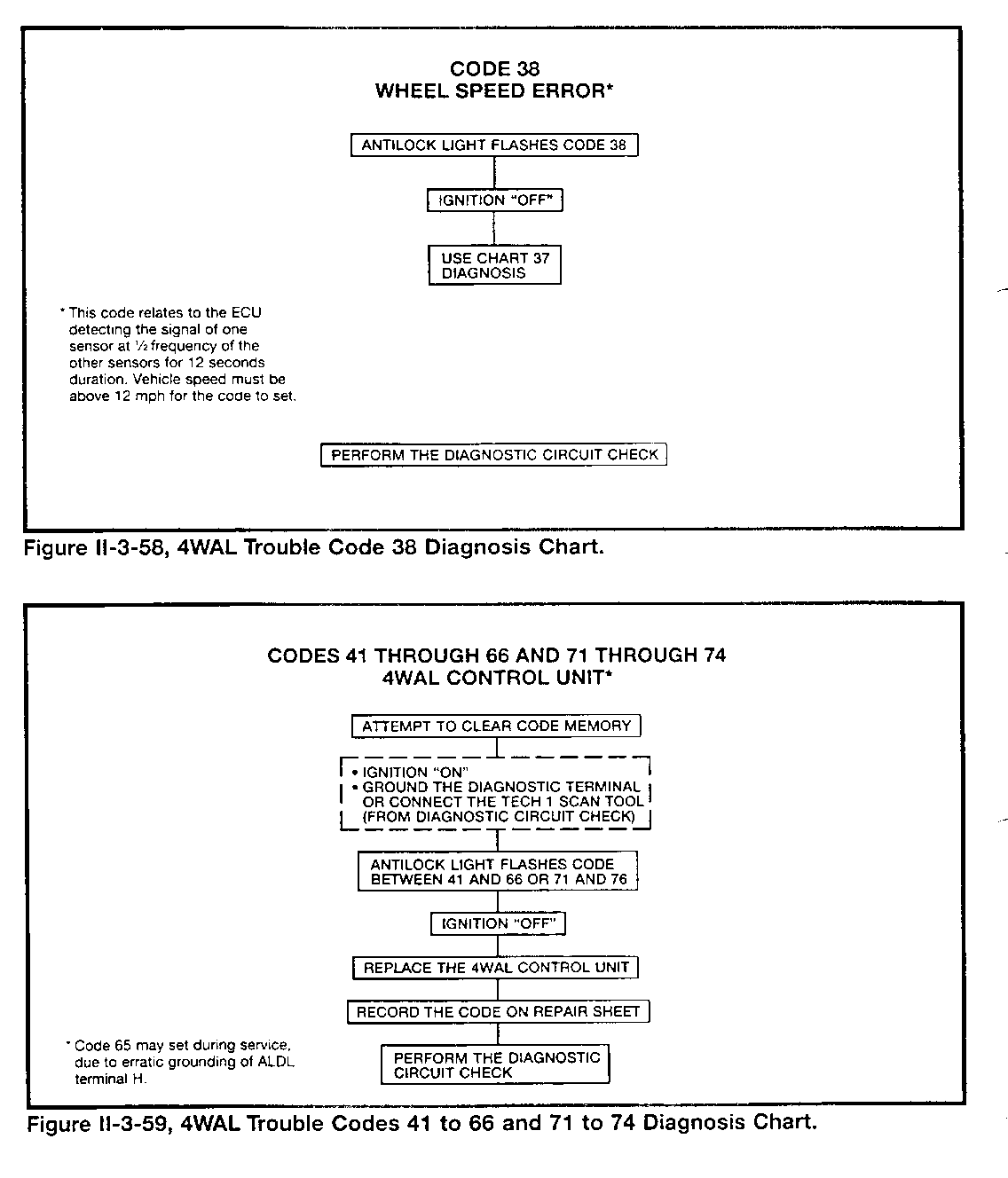
- Code 38 - One sensor has a signal indicating speed twice that of the other sensors, above 12 mph
THE "ANTILOCK" LIGHT
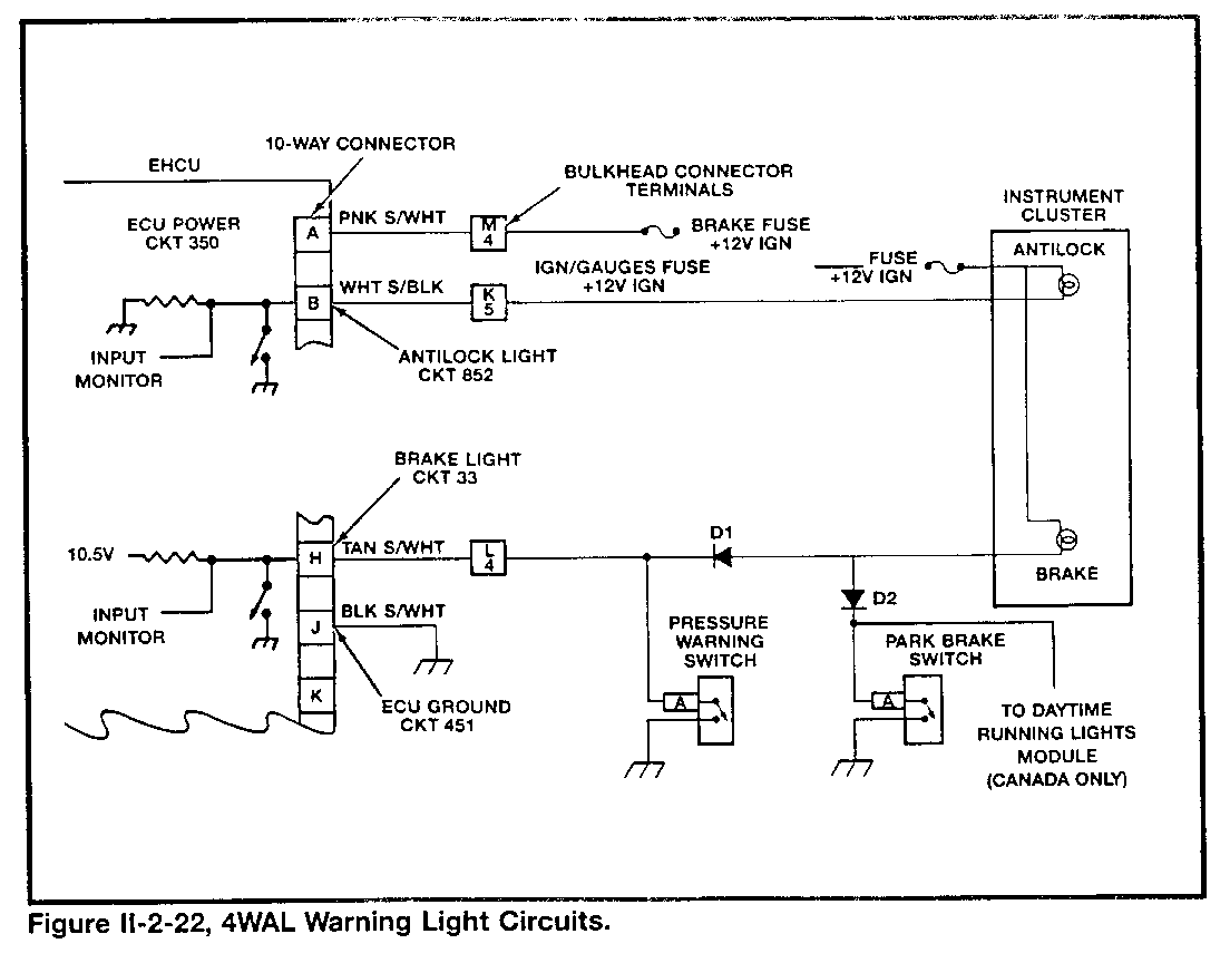
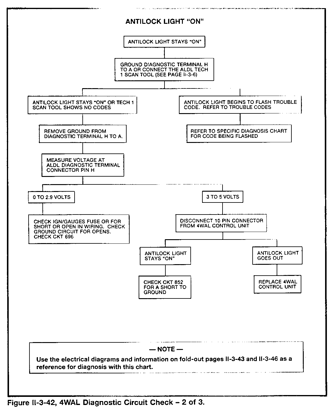
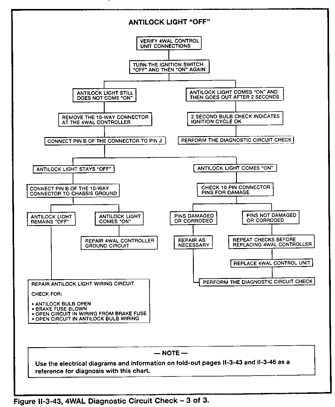
The 4WAL ECU uses a new amber-colored "Antilock" warning light to alert the driver of a malfunction it has detected. It completes the "Antilock" light circuit, using the 10-way connector terminals B and J (Figure 11-2-22).
The ECU completes the circuit for the "Antilock" light by providing a ground. It operates the light by making it do one of two things:
Light steadily:
- During an initial test at the beginning of an ignition cycle - When a system malfunction exists
Flash ON and OFF (to present trouble code information) when a service technician grounds the ALDL diagnostic request terminal H.
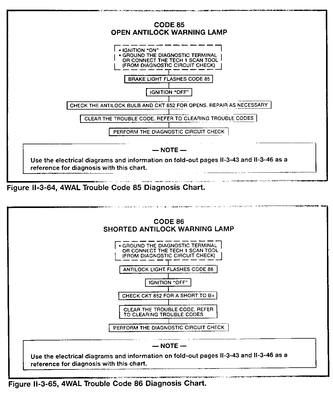
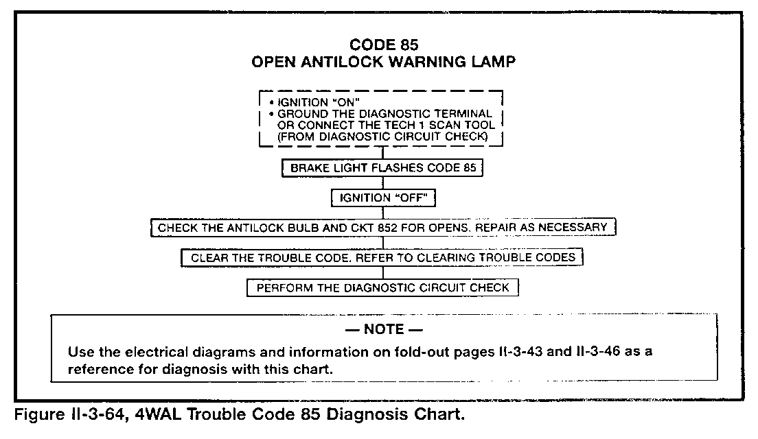
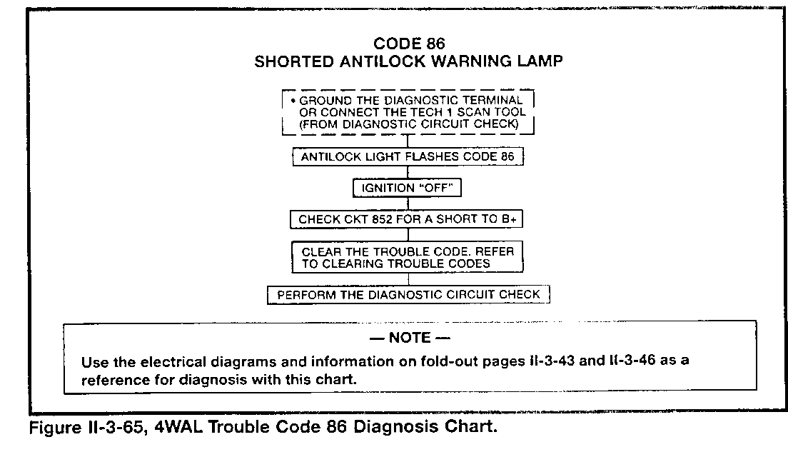
An input monitor circuit within the ECU allows it to detect an open or shorted circuit for the "Antilock" light during the initial test for each ignition cycle:
- When the "Antilock" light is unlit, the voltage at the monitoring point within the ECU will be high.
- The voltage at the monitor point will be low when the ECU grounds the "Antilock" light circuit.
If the ECU monitors low voltage at terminal B before it attempts to ground the light circuit, it determines that a short or open circuit exists. If the ECU monitors high voltage after it attempts to ground the "Antilock" light circuit, it determines that a short to voltage condition exists.
In the case of either malfunction, the ECU will take diagnostic action:
- Complete the "Brake" light to alert the driver - Store a trouble Code 85 (open) or 86 (short)
THE "BRAKE" LIGHT
The vehicle instrument cluster has a red "Brake" warning light to alert the driver to the following conditions:
- Parking brake is applied - A hydraulic failure in either the front or rear channel - A 4WAL ECU detected trouble code (an "Antilock" light circuit problem exists).
An ignition switch-controlled circuit provides power to the "Brake" light in the vehicle instrument cluster. There are three parallel paths to chassis ground to complete the circuit (Figure 11-2-22):
- Through the parking brake switch contacts
- Through the combination valve differential pressure switch contacts
- Through the ECU circuitry
The ECU completes the "Brake" light circuit for several reasons:
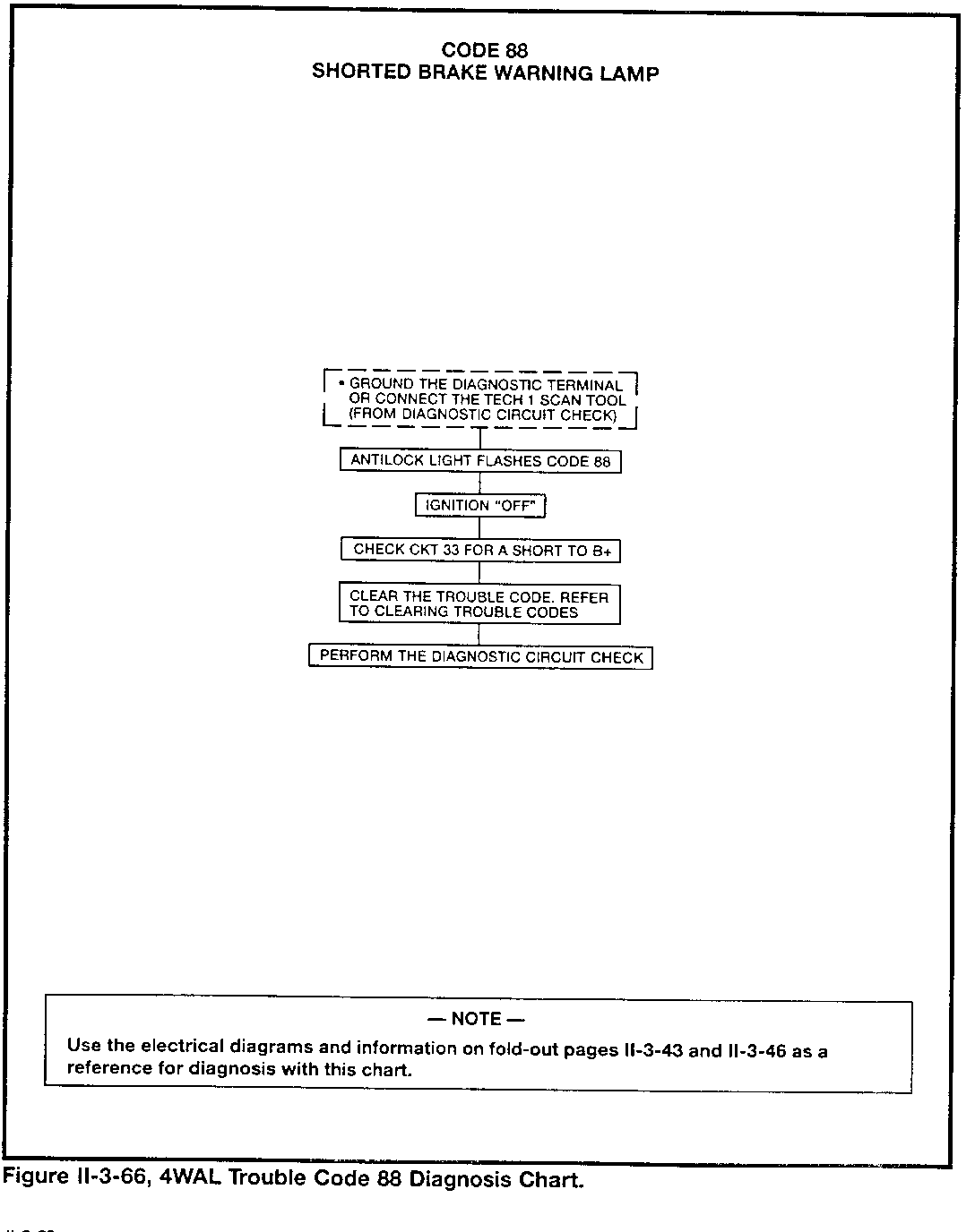
- To conduct a "Brake" light circuit check at the beginning of each ignition cycle
- To alert the driver of a 4WAL system malfunction related to the foundation brakes
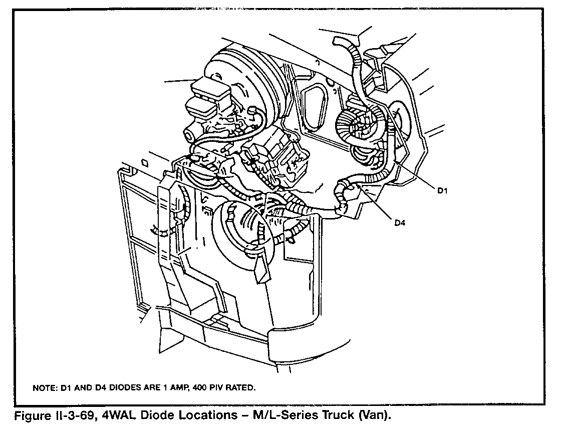
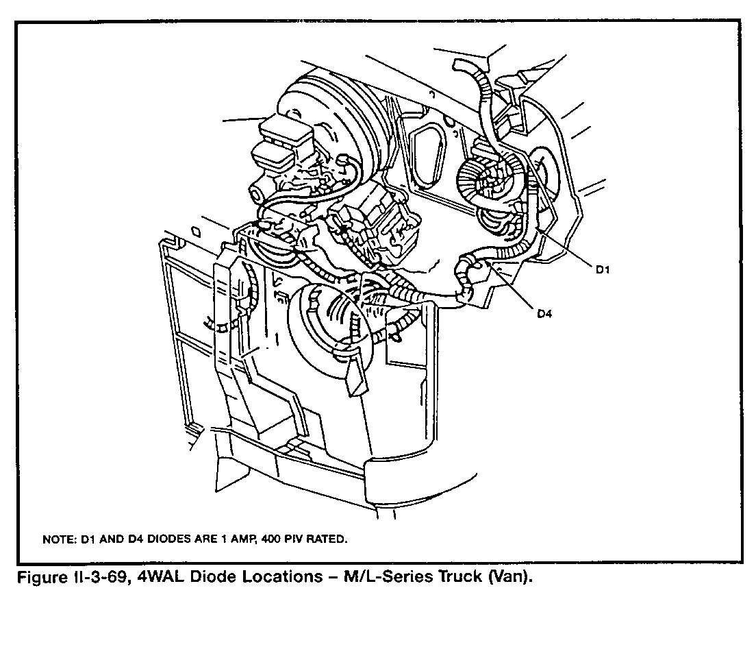
The ECU also monitors the "Brake" light circuit. An isolation diode (D1) allows an ECU monitor circuit to be grounded by the differential pressure switch, which also provides a complete circuit for the "Brake" light. As a diagnostic action to this condition, the ECU will adjust its antilock control programming.
The operation of the park brake switch does not affect the ECU monitor circuit for the "Brake" light, due to the blocking action of D1. Another isolation diode (D2) prevents the park brake switch from providing an input to the daytime running lights module (used in Canadian vehicles).
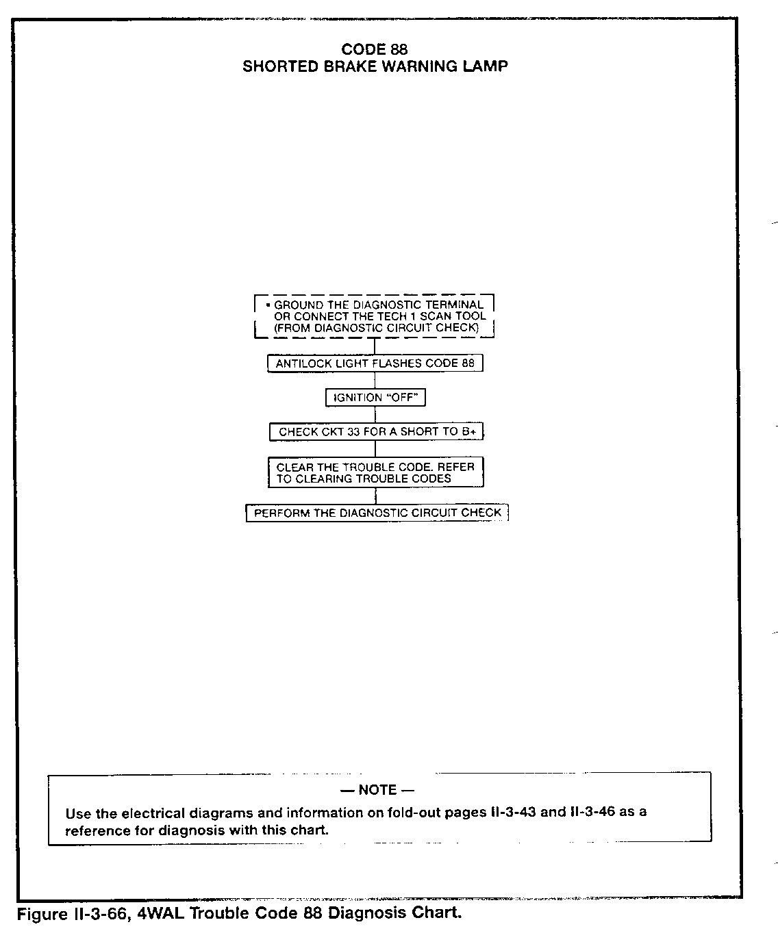
The ECU checks the "Brake" light circuit at the beginning of each ignition cycle. If the ECU monitors low voltage at terminal H before it attempts to ground the light circuit, it determines that a short exists. Diagnostic action for this detected condition includes storing a trouble Code 88.
II.3, Diagnosis
Overview
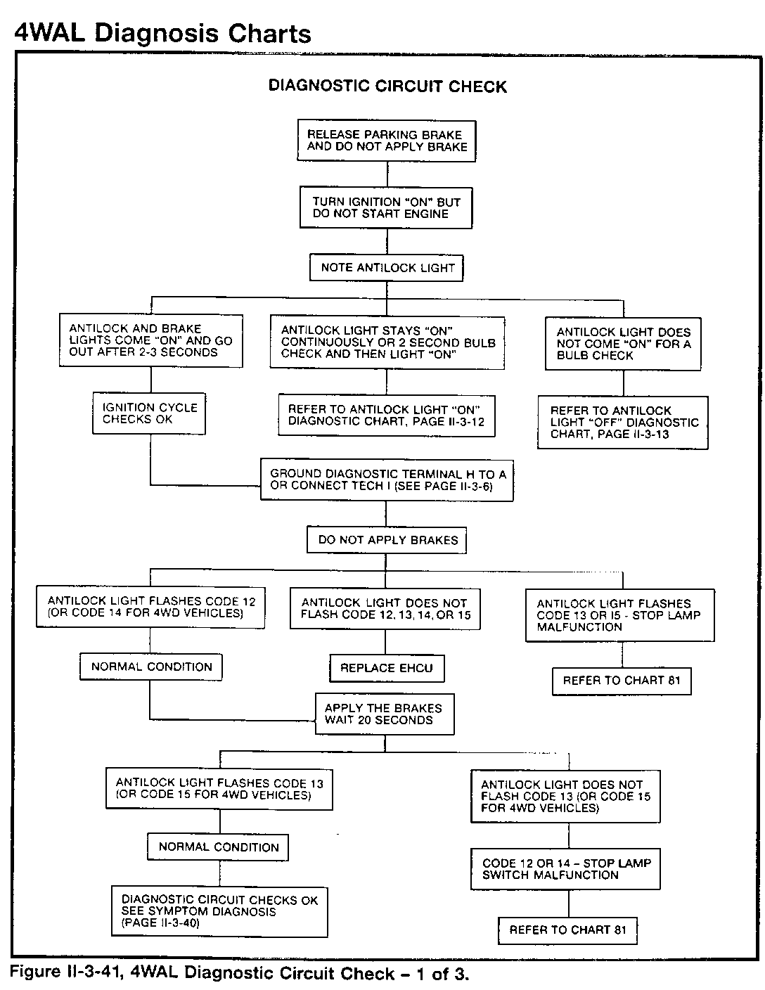
The overall diagnostic sequence involves these steps:
1. Perform the Diagnostic Circuit Check.
Refer to pages II-3-16 through II-3-18.
NOTE
Always perform the diagnostic circuit check FIRST to avoid misdiagnosis.
2. Follow the chart related to a stored trouble code, if necessary.
Refer to pages II-3-19 through II-3-39.
- NOTE -
If no codes are stored, refer to symptom diagnosis (page II-3-40).
3. Make the repair related to a trouble code, if necessary.
Refer to the Service Section of this book.
4. Clear the ECU trouble code memory.
5. Repeat the Diagnostic Circuit Check.
4WAL Diagnosis Without Tech 1
The 4WAL ECU uses the "Antilock" light to alert the driver to a problem it has detected. A technician can follow the charts of the Diagnostic Circuit Check (pages II-3-16 through II-3-18) based on observing the "Antilock" light.
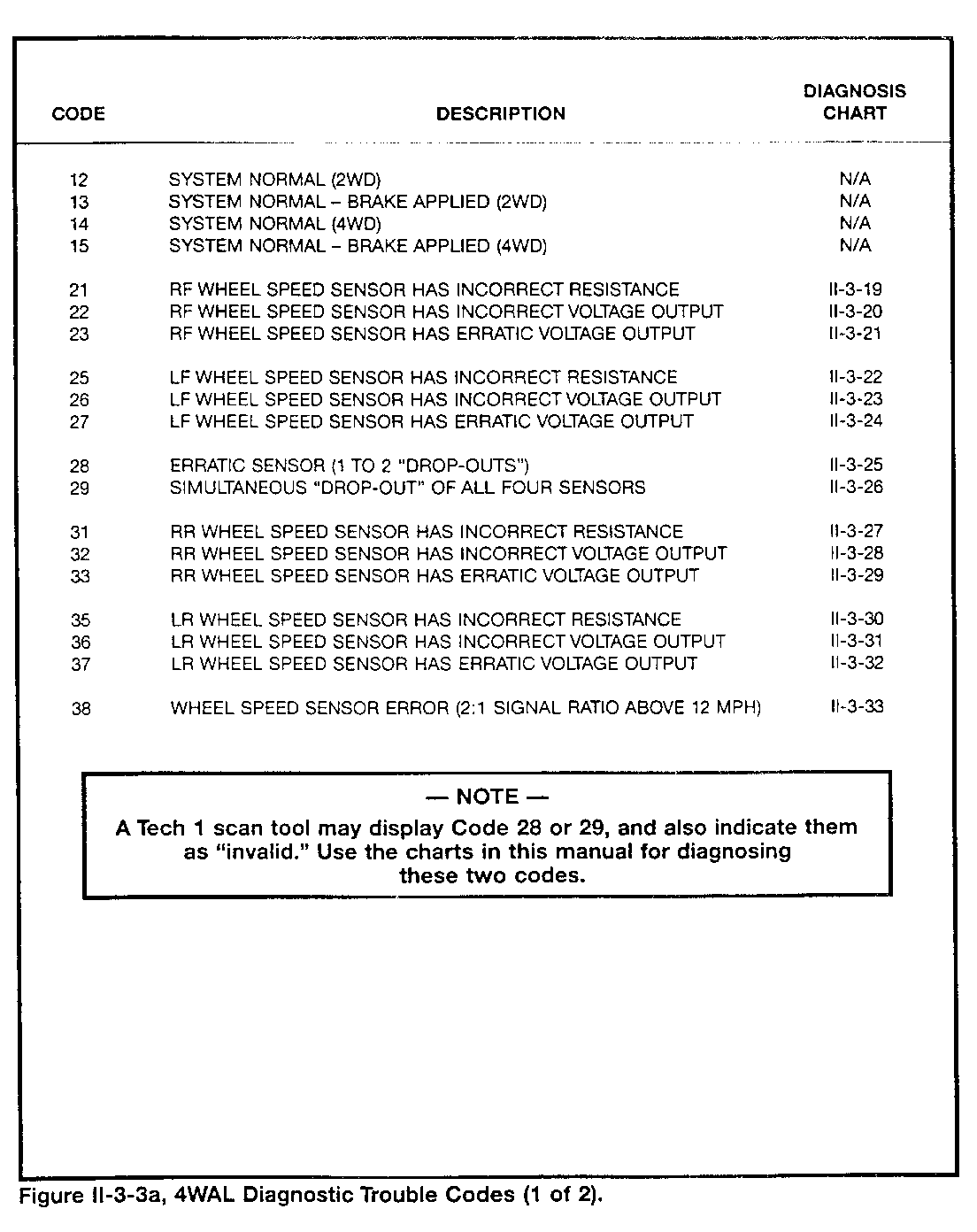
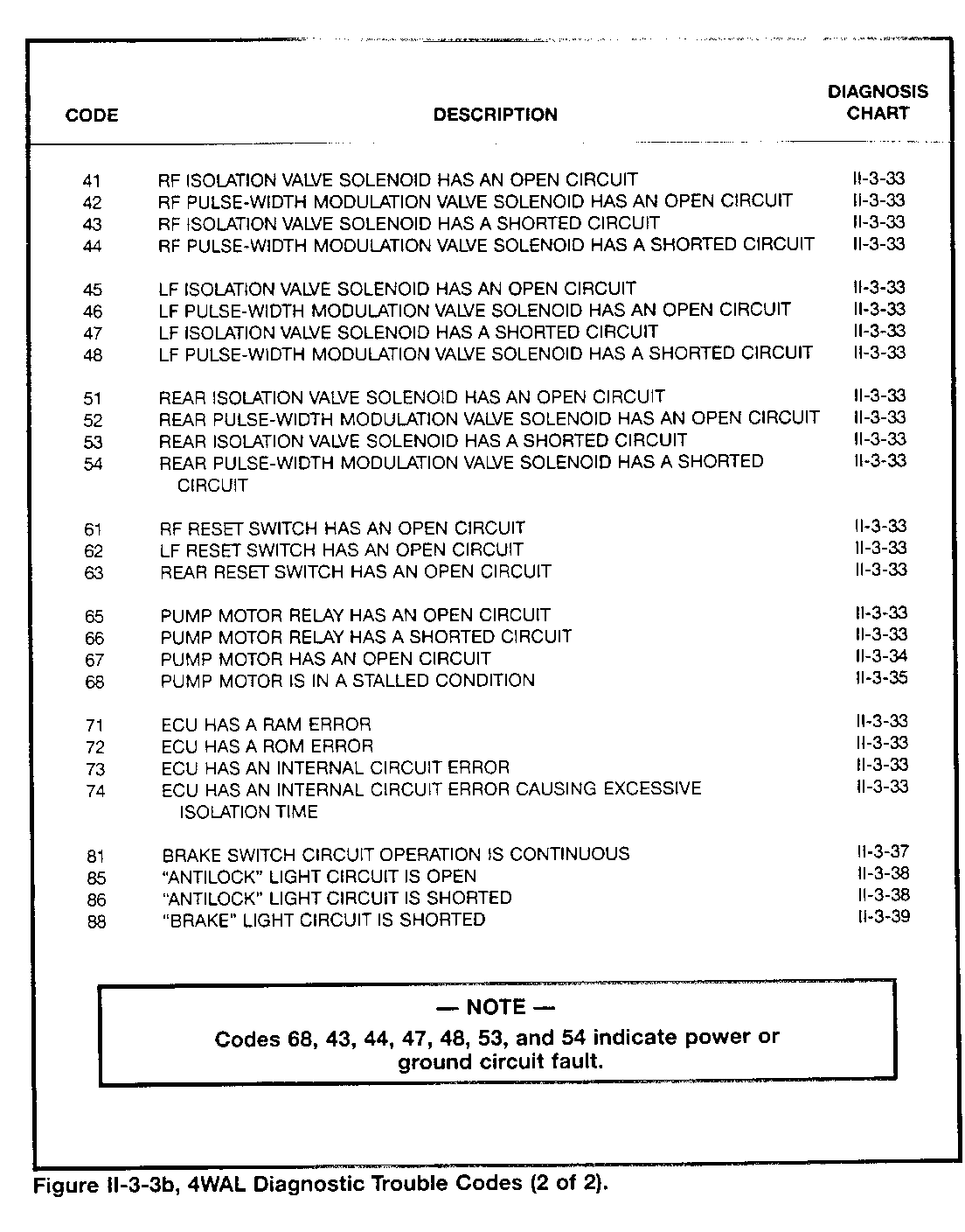
The ECU also stores diagnostic trouble codes for the problems it detects (Figure II-3-3 on pages II-3-3 and II-3-4). The ECU stores as many codes as necessary and can store codes for both current and past detected faults.
The ECU runs an Ignition Cycle series of tests in order to initially detect any problems. The Ignition Cycle has two checks:
- Initial checks when the ignition switch is turned to the "run" position.
- Checks when the vehicle first reaches a speed of 8 mph with the brake pedal released.
NOTE
The ECU will delay running the 8 mph checks if the brake switch signal is 0 volts, indicating that the brake pedal is pressed. It will run the checks as soon as the brake switch signal is 12 volts, indicating that the brake pedal is released.
The initial checks may result in the detection of problems related to these codes: 21, 25, 31, 35, 71, 72, 73, 74, 85, 86, and 88.
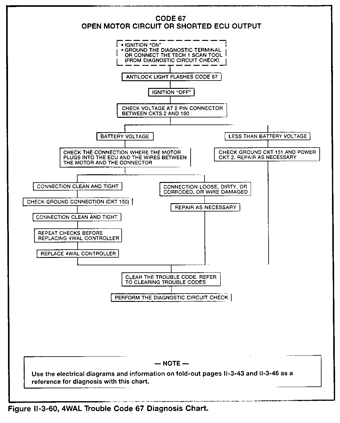
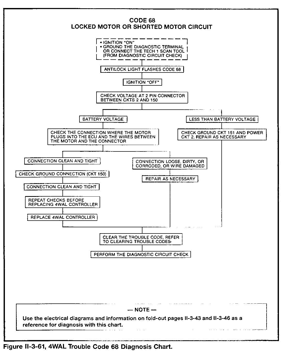
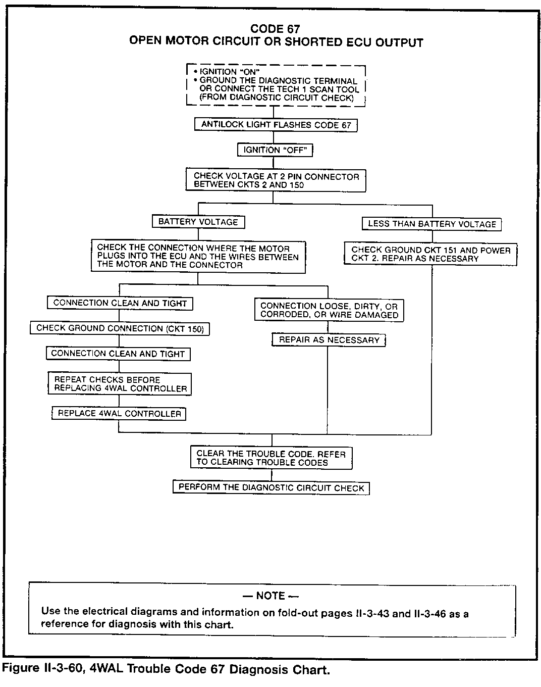
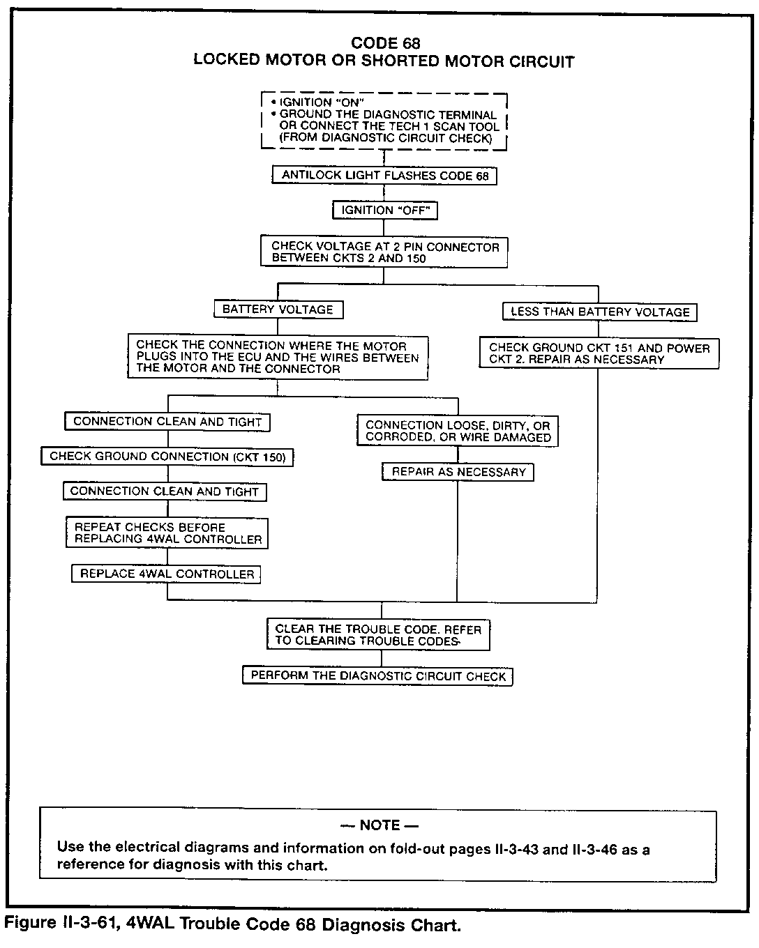
The 8 mph checks may result in the detection of problems related to these codes: 41, 42, 43, 44, 45, 46, 47, 48, 51, 52, 53, 54, 61, 62, 63, 65, 66, 67, and 68.
The ECU may detect wheel speed sensor problems at any speed above 3 mph and may store these codes: 22, 23, 26, 27, 32, 33, 36, 37, and 38.
A technician requests the ECU to flash the "Antilock" light ON and OFF to indicate the number of its stored code by doing the following:
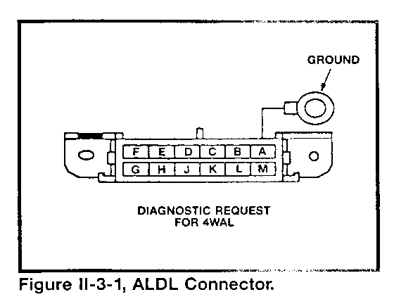
- Turning the ignition switch to the "run" position. - Installing a jumper wire between ALDL terminals H and A (or chassis ground). Refer to Figure II-3-1. - Waiting two to three seconds.
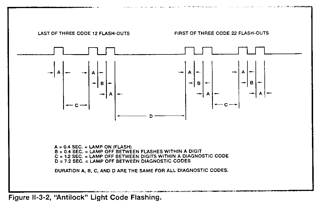
Watching the "Antilock" light flash ON and OFF in a manner similar to the ECM for the fuel/emissions system (refer to Figure II-3-2):
- The light may flash a Code 12 (brake pedal released for 2WD vehicles) or Code 14 (brake pedal released for 4WD vehicles) three times before it flashes its stored codes three times each in a continuous series.
- The light may flash a Code 13 (2WD) or Code 15 (4WD) instead of Codes 12 or 14, if the brake pedal is pressed (or switch circuit is open), followed by the code display
A technician clears the ECU trouble code memory by doing the following:
- Turning the ignition switch to the "run" position.
- Installing the ALDL terminal H to A (or chassis ground) jumper wire.
- Waiting two seconds.
- Removing the jumper wire for two seconds.
- Repeating the grounding and ungrounding procedure two more times.
- Checking that the memory is cleared by making a diagnostic request.
- Turning the ignition switch to the "OFF" position.
A technician may also request the ECU to perform a function test by grounding ALDL terminal H once (for two seconds), then ungrounding it.
4WAL Diagnosis With Tech 1
A technician may use a Tech 1 scan tool to assist in the diagnostic procedure. If the Tech 1 has a serial number between xx000001 and xx002000, it cannot use the 1988-1990 GM-Truck Antilock Brakes cartridge required to perform this form of diagnosis.
Use the Tech 1 and the cartridge with a special RWAL/4WAL adapter. Follow the instruction book, and use pages II-3-2 through II-3-3 of this book as a guide.
With the Tech 1, a technician:
- Checks the ALDL connector terminal H voltage
- Views diagnostic data:
- Trouble codes - 2WD/4WD status (T-Series truck) - LF wheel speed (mph) - RF wheel speed (mph) - LR wheel speed (mph) - RR wheel speed (mph) - LF channel reset switch status (open/closed) - RF channel reset switch status (open/closed) - Rear channel reset switch status (open/closed) - Brake switch status (ON/OFF) - "Antilock" light status (ON/OFF) - "Brake" light status (ON/OFF) - Soft fault status (yes/no)
- Performs an electro-hydraulic functional test
- Checks trouble codes currently stored by the 4WAL ECU in block 0
- Clears the ECU trouble code memory
- Performs snapshot sampling of the diagnostic data listed above in three phases:
- Set-up - Data capture - Data display: - Sample-by-sample - Individual parameter-by-sample
- Views miscellaneous data:
- 4WAL ECU PROM identification - History code information:
* Number of ignition cycles before a particular trouble code has been stored * The number identification of the particular trouble code * Number of ignition cycles after a particular trouble code has been stored * Number of antilock braking stops in the history blocks of the EHCU * Number of trouble codes stored in the history blocks of the EHCU
GETTING STARTED
A. Insert the 1988-90 GM-Truck Antilock Brakes cartridge into the Tech 1 master slot at the bottom of the unit. Make sure that no other cartridge is in the auxiliary slot.
B. Turn the vehicle ignition switch to the "OFF" position.
C. Connect the Tech 1 to battery power, using the vehicle cigarette lighter.
D. Attach the Tech 1 to the RWAL/4WAL adapter.
E. Insert the RWAU4WAL adapter connector into the ALDL connector.
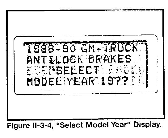
F. Observe the display (Figure II-3-4). If the display indicates a problem, check and repair the following:
Cartridge installation Power supply for the Tech 1 Tech 1 itself
A. Turn the ignition switch to the "run" position.
B. Press the numeric keys indicating the last two digits of the model year of the vehicle.
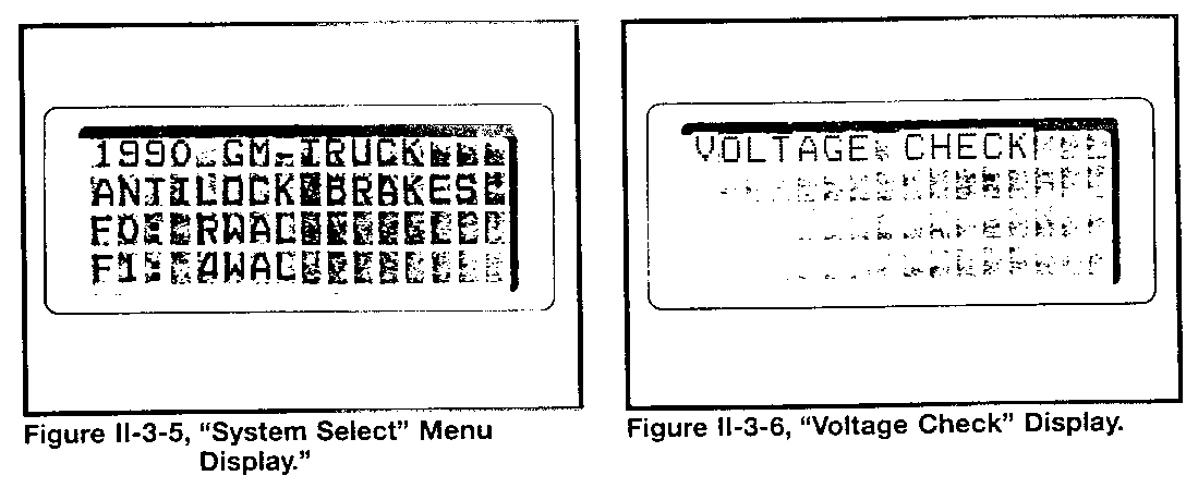
C. For model year 1990, press the FO key to select 4WAL tests (Figure II-3-5).
ALDL PIN H VOLTAGE CHECK
A. Observe the display (Figure II-3-6). The Tech 1 automatically performs a voltage check of ALDL connector pin H voltage.
If the voltage is normal, the Tech 1 will next display the "Mode Select" menu. No indiction of normal voltage appears on the display.
- NOTE -
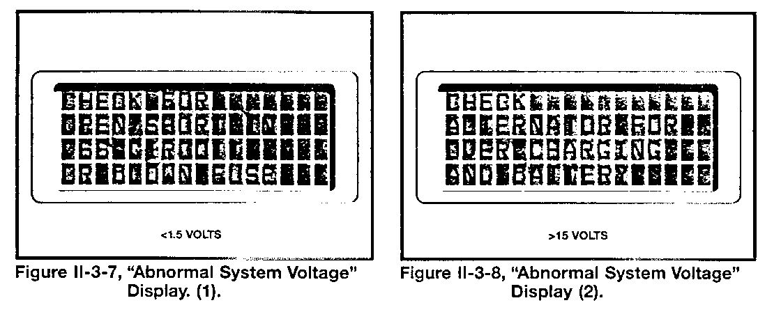
The display shown in Figure II-3-7 indicates low voltage. Failure to use the RWAL/4WAL adapter will result in this display.
- NOTE -
Figure II-3-8 shows a high voltage indication.
SELECTING A 4WAL TEST MODE
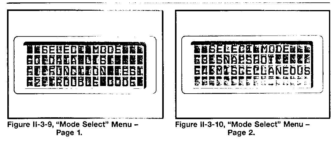
A. Observe the display (Figures II-3-9 and II-3-10). The Tech 1 will sequence between two pages of the mode select menu.
Press the F0 key to view diagnostic data (see page II-3-8 for the procedure).
Press the F1 key to perform an electro-hydraulic functional test (see page II-3-10 for the procedure).
Press the F2 key to view any stored trouble code(s) (see page II-3-11 for the procedure).
Press the F3 key to use the snapshot feature (see page II-3-11 for the procedure).
Press the F4 key to view miscellaneous data (see page II-3-14 for the procedure).
VIEWING DIAGNOSTIC DATA
A. Use the "yes" and "no" keys to scroll through the data.
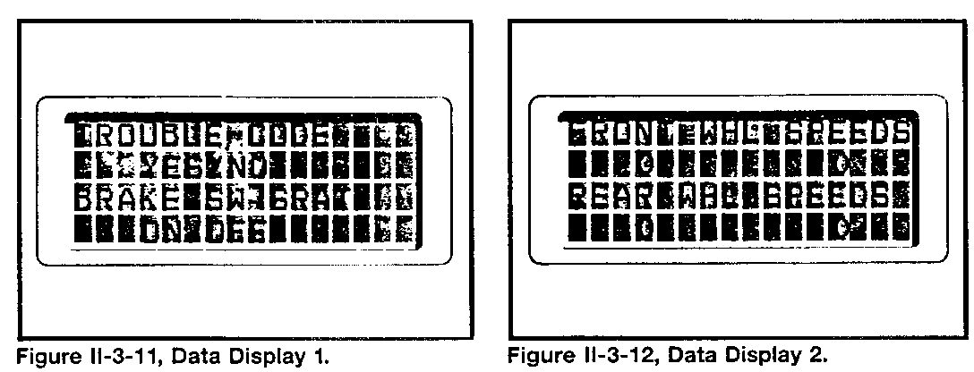
Parameters are displayed in pairs:
- Trouble code/brake switch status (Figure 11-3-11).
- NOTE -
Brake switch ON status means a 0-volt signal to the ECU, and OFF means a 12-volt signal
Front wheel speeds/rear wheel speeds (Figure II-3-12).
- NOTE -
Vehicle speeds will drop from 5 mph to 0 mph as a normal ECU function.
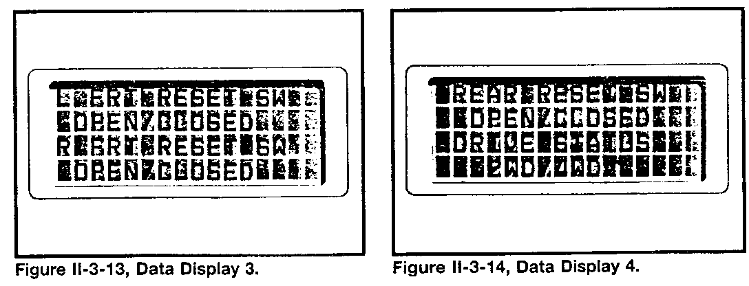
- LF reset switch/RF reset switch status (Figure II-3-13).
-NOTE -
Reset switch is normally closed, and open during pressure reduction in antilock braking.
- Rear reset switch/2WD-4WD switch status (Figure II-3-14).
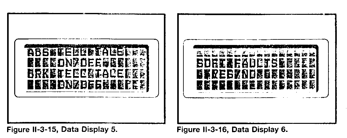
- "Antilock" and "Brake" light status (Figure II-3-15).
B. Use the soft faults status to assist in locating loose connections that may cause intermittent problems or ECU-detected faults (Figure II-3-16).
Wiggling connectors while viewing the display may find a cause for a hard-to-find conditions in wheel speed sensor circuits.
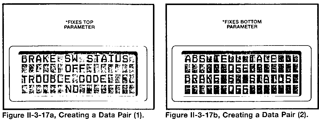
C. Change the data parameter pairs:
Scroll through the data until a desired upper parameter appears in the display
Press F0 to fix the parameter
- Note the asterisk indicator (Figure II-3-17a)
Scroll through the lower parameters, while the upper parameter remains fixed, until a desired parameter appears.
Press F1 to fix the lower parameter
- Note the asterisk indicator (Figure II-3-17b)
Press F1 to unfix an upper parameter, and press
F0 to unfix a lower parameter
D. Continue viewing the data parameter information.
E. Press EXIT to return to the "Mode Select" display
PERFORMING A FUNCTIONAL TEST
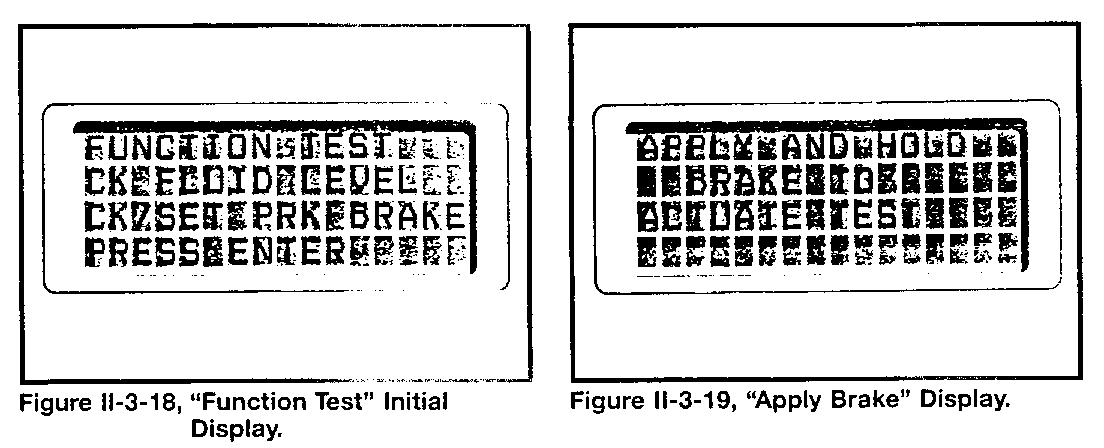
A. Observe the display (Figure II-3-18).
Check the brake reservoir and apply the park brake.
Press ENTER and observe the display (Figure II-3-19).
Apply foot pressure to the brake pedal.
Observe the "Test Being Conducted" display
The Tech 1 is causing the 4WAL ECU to run a Drive Cycle Test.
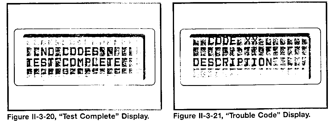
B. Observe the display (Figure II-3-20).
"Test complete" indicates that the 4WAL ECU performed a Drive Cycle Test without detecting a hydraulic control unit fault.
If the 4WAL ECU detected a problem, the display will show the related trouble code information (Figure II-3-21). Make repairs, and recheck the system.
Press EXIT to return to the "Mode Select" display.
VIEWING THE STORED TROUBLE CODE(S)
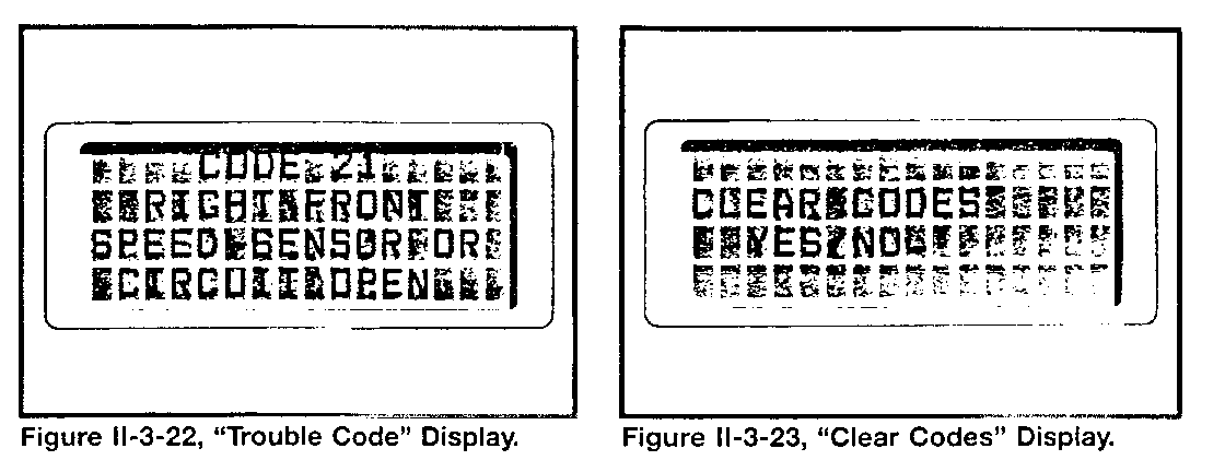
A. Observe the display (Figure II-3-22).
The Tech 1 will display one page for each trouble code stored.
Press the "down" or "up" key to advance or hold the display pages.
B. When all stored codes have been displayed, observe the screen (Figure II-3-23).
Press YES or NO to clear the ECU trouble code memory.
Press EXIT to return to the "Mode Select" display.
USING SNAPSHOT
A. Set-Up Phase
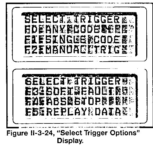
Observe the display (Figure II-3-24).
- Press any one of the keys listed as a trigger for the snapshot action.
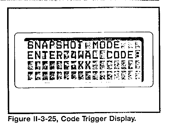
- Enter the two-digit trouble code number, if "single code" is the trigger (Figure II-3-25).
B. Data Capture Phase
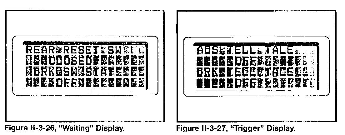
Observe the display (Figure II-3-26) while scrolling through the data displays.
- Note the "W" in the lower right corner of the display that shows the Tech 1 is waiting for the snapshot trigger to appear.
Force a snapshot trigger, using the F9, EXIT, or ENTER key
- Note the "T" in the display lower right corner (Figure II-3-27).
- Allow time to fill the data buffer (32 seconds).
- Press EXIT twice to end the Data Capture phase if the Tech 1 has not already proceeded to it.
C. Data Display Phase
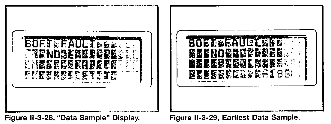
Observe the display (Figure 11-3-28).
- Use the "up" and "down" keys to scroll through the data samples.
- Note the number of the data sample (lower right corner of the display).
- Press the F4 key to view the earliest sample (Figure II-3-29).
Data sample information:
Each frame is a complete list of 4WAL data (175 milliseconds in length)
There are 186 frames recorded before the trigger (indicated as "-")
There are 186 frames recorded after the trigger (without a "+" indication)
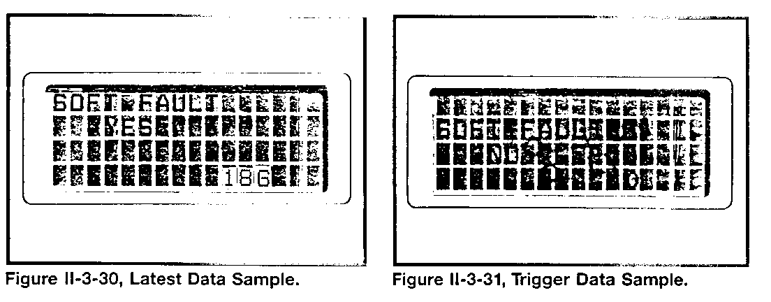
- Press the F6 key to view the latest sample (Figure II-3-30).
- Press the F5 key to view the trigger sample (Figure II-3-31).
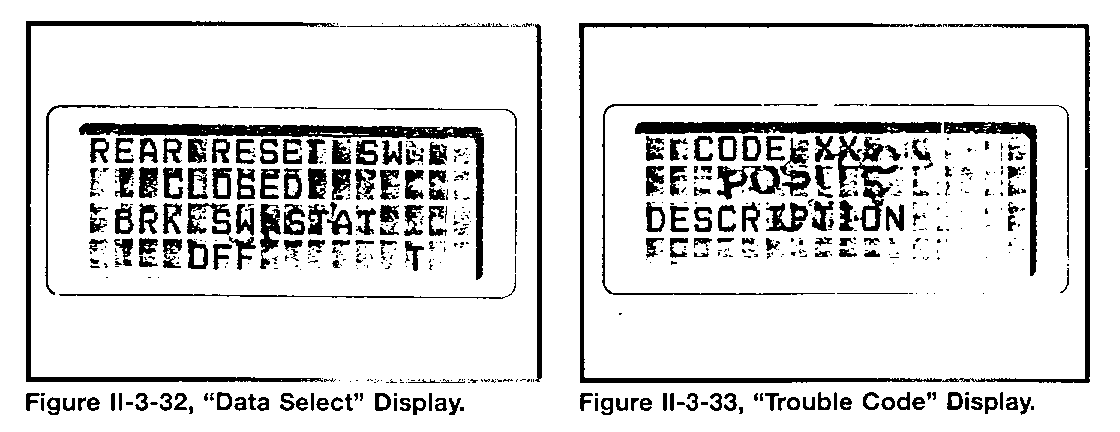
Observe the display (Figure II-3-32). Press YES to view the sample information by parameters, rather than entire samples.
- Choose a parameter to view throughout the sample data.
- Press the F2 key to view any stored trouble codes while viewing sample data (Figure II-3-33).
- Press EXIT three times to return to the "Select Trigger" display
VIEWING MISCELLANEOUS DATA
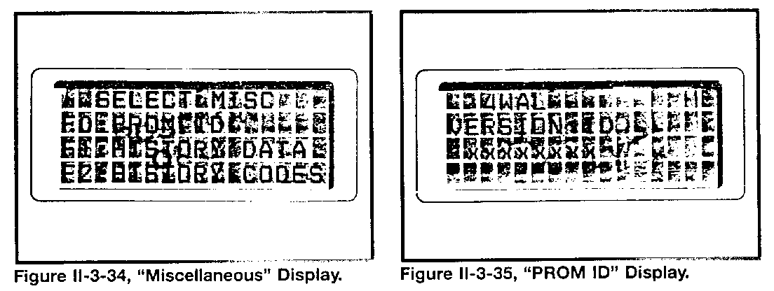
A. Observe the display (Figure II-3-34).
Press the F0 key to view the 4WAL ECU PROM identification characters.
B. Observe the display (Figure II-3-35).
Compare the 4WAL ECU PROM identification to related service information requesting it.
Press EXIT to return to the "Miscellaneous" display.
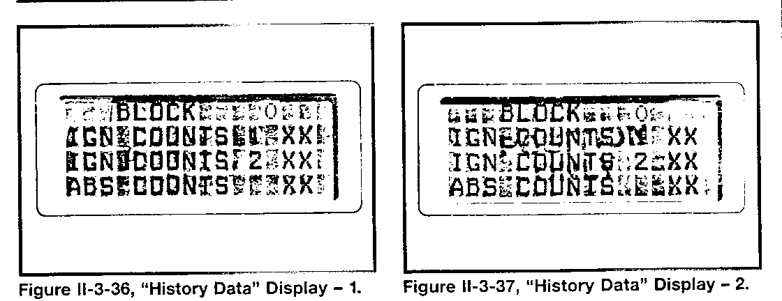
C. Press the F1 key to view the history data information.
Observe the display (Figure II-3-36).
- The history block number is 0.
- The "ignition counts 1 " number relates to drive cycles before a detected fault.
- The "ignition counts 2" number relates to drive cycles after a detected fault (Figure II-3-37).
Counter numbers are: 0 for 0 to 16 cycles 1 for 17 to 32 cycles 2 for 33 to 48 cycles 3 for 49 to 64 cycles
- The "ABS counts" number relates to the total number of antilock control braking maneuvers to 0 mph.
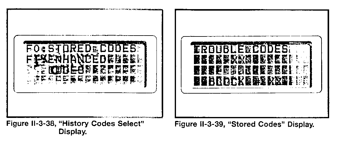
D. Press the F2 key to view the history codes information.
Observe the display (Figure II-3-38).
- Press F0 to view history blocks by number and description.
- Press the F1 key to view code numbers and descriptions.
Observe the display (Figure II-3-39).
- Note that you may search for all trouble codes stored in a particular history block.
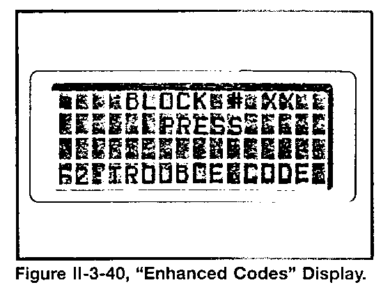
E. Press the F1 key to view trouble code descriptions stored in each block.
Observe the display (Figure II-3-40).
- Press the F2 key to read a description of each code stored in a particular history block.
F. Press EXIT to return to the "Miscellaneous" display.
Summary of History Block Operation
When any code is latched, the system is disabled until a repair is made and the code is cleared. From the time the code is set and latched to the time the code is cleared, it resides in block 0. The IGN counter 1 records the number of drive cycles before the code is set. The ABS counter records the number of full ABS stops before the code is set. The IGN counter 2 is incremented up to the time the code is cleared. When the code is cleared, block 0 moves to block 1 and block 0 is ready to record new information.
4WAL Symptom Diagnosis - Non-Code Conditions
Condition: Brake pedal pulses (or "ratchets") downward during a soft-to-moderate braking maneuver on dry pavement.
Diagnostic check:
Check for 'grabby' brakes:
- Remove the "Brake" fuse (ignition switch "off")
- Drive the vehicle to evaluate the hydraulic system operation:
- Inspect the mechanical and hydraulic parts of the brake system if the condition remains. Make necessary repairs.
- Check each wheel speed sensor for a weak signal if the condition remains.
- Check the sensor output voltage (1 Volt AC minimum)
- Check the sensor mounting
- Check the sensor tone wheel for cracks
Condition: Increased brake pedal travel or "soft pedal."
Diagnostic check:
Check the brake system for a low reservoir fluid level:
Level is low:
- Inspect the hydraulic system for fluid leaks. Make necessary repairs and bleed the entire hydraulic system.
Level is good:
- Depress the brake pedal for one minute (while the engine is running in Park), and observe the "Antilock" warning light for an indication of a stored trouble code:
Code stores:
- Perform trouble code diagnosis
No code stores:
- Replace the EHCU (internal leak)
Condition: Wheel pull during hard braking (wheel lock causes antilock control action), but not during soft-to-moderate braking on dry pavement.
Diagnostic check:
- Inspect the mechanical and hydraulic parts of the brake system:
- Linings and discs/drums (for glazing)
- External leaks
- Hydraulic pressure during braking at each wheel cylinder
- Drain, refill, and bleed the entire brake system (including the EHCU)
Condition: Noise at 8 mph (at the beginning of each ignition cycle).
Diagnostic check:
- Verify that the noise level of the EHCU during an ignition cycle check is normal:
- Normal:
- Explain system operation to the customer, using the owner's manual.
- Abnormal:
- Check the EHCU for physical contact with other vehicle parts. Make necessary repairs.
- Check the EHCU-to-mounting bracket bolt torque (six bolts at 6 to 8 lb. ft.).
4WAL Symptom Diagnosis - Code Conditions
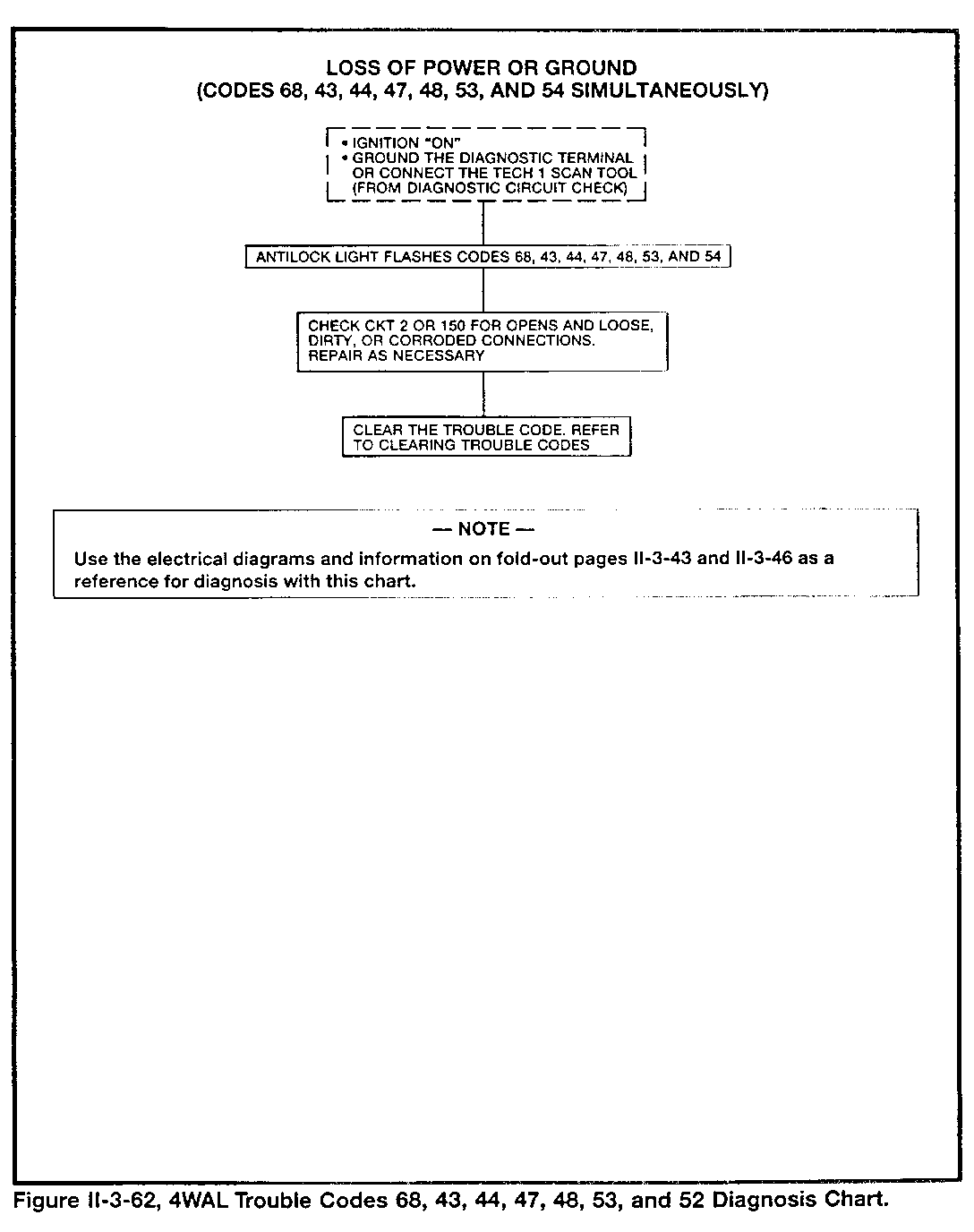
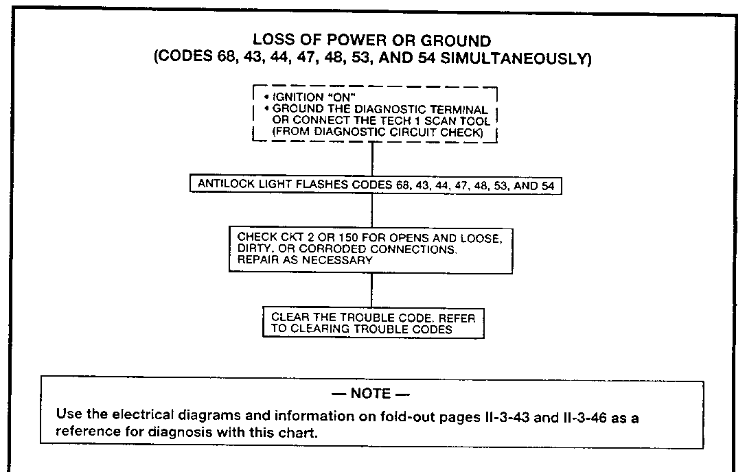
Condition: muitiple codes setting during an 8 mph test or function test (68, 43, 44, 47, 48, 53, 54)
Possible Cause: Loose or corroded power (B+ and/or ground) circuits
Checks: Terminal condition at EHCU power connector (2-way), B+ junction block or ground junction
Condition: Code 65
Possible Cause: Erratic grounding of ALDL terminal H during service procedures
4WAL Symptom Diagnosis - Normal Conditions
The following are normal operating features of the 4WAL system and should not be confused with "problem" conditions:
- A pump noise during the 8 mph test (once per driving cycle)
- Pedal movement (greater than normal) during antilock braking on mixed traction road surfaces (dry pavement-to-ice, for example)
- Pump noise and pedal movement (vibration) during any antilock stop
Service Information
HYDRAULIC SYSTEM FLUSHING/BLEEDING
The 4WAL hydraulic system requires flushing at intervals related to regularly scheduled brake lining replacemen Use one quart of DOT 3 fluid to bleed the existing system fluid from all channel passages. This will remove any moisture which may cause component corrosion.
- NOTE -
Do not use DOT 5 (silicone) brake fluid. System damage may result.
Manual Bleeding
1. Deplete the vacuum reserve by applying the brakes several times.
2. Fill the master cylinder with DOT 3 brake fluid. During bleeding, keep the master cylinder at least one-half full at all times.
3. Bleed the wheel circuits in the following order: left rear, right rear, left front, right front.
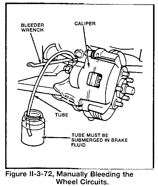
4. With the proper box-end wrench over the bleed valve, attach a bleeder tube to the valve. Allow tube to hang, submerged in brake fluid, in a clean glass jar (Figure II-3-72).
5. Fully depress the brake pedal and open the bleede, valve.
6. Close the bleeder valve and release the brake pedal.
7. Repeat steps 5 and 6 until all air has been evacuated from the system. Refill the master cylinder reservoir as necessary to maintain brake fluid level and prevent the entry of air into the hydraulic system.
8. If necessary, repeat the bleeding procedure at any wheel circuit that is to be bled.
9. Check the brake pedal for a "spongy" feeling, and repeat the bleeding procedure as necessary.
- NOTE -
Install the HPA bleed valve stem depressor tools during hydraulic system bleeding. Also, open the two side bleed screws 1/4- to 1/2-turn. Remove tools and close valves when finished.
Pressure Bleeding
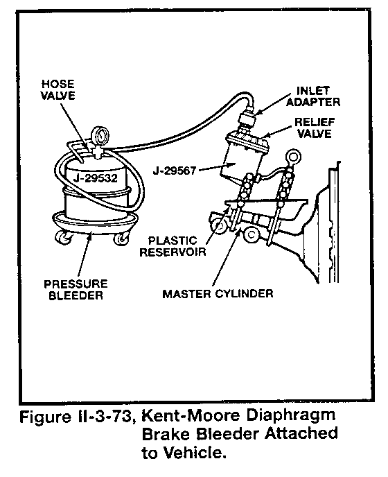
The following procedure refers to the usage of Kent-Moore Diaphragm Brake Bleeder J-29532 or its equivalent (Figure 11-3-73):
1. Install the correct bleeding adapter to the master cylinder.
2. Ensure that the pressure bleeder fluid tank is at least one-third full of Delco Supreme #11 brake fluid, or its DOT 3 equivalent.
3. Charge the pressure bleeder air tank to between 20 and 25 psi (140 to 175 kPa).
4. Attach the hose to the master cylinder bleeder adapter and open the pressure tank fluid valve.
5. Bleed the wheel circuits in the following order: left rear, right rear, left front, right front.
6. With the proper box-end wrench over the bleeder valve, attach a bleeder tube to the valve. The discharge end of the bleeder tube must be submerged in brake fluid in a clean glass jar.
7. Open the bleeder valve at least 3/4-turn and allow fluid to flow until air-free fluid flows from the bleeder tube.
8. Close the bleeder valve; be sure that it is properly sealed.
9. Repeat steps 6 through 8 until all air has been evacuated from the system.
10. Check the brake pedal for a "spongy" feeling, and repeat the bleeding procedure as necessary.
11. Properly dispose of all fluid bled from the brake system.
12. Close the pressure tank fluid valve, and disconnect the bleeding equipment from the brake bleeder adapter.
13. Remove the bleeder adapter from the master cylinder. Clean up any fluid spilled during adapter removal.
14. Fill the master cylinder reservoirs to the proper level.
15. Install the master cylinder diaphragm and cover.
Vacuum Bleeding
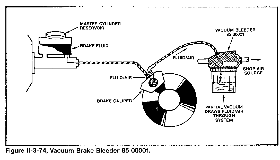
1. Connect Vacuum Bleeder 85 00001 to a source of compressed air (Figure II-3-74).
2. Uncap brake master cylinder reservoir.
3. Depress lever on the top of the bleeder tool to create a vacuum. Use the bleeder hose to vacuum the hold brake fluid out of the reservoir. Release the lever.
4. Fill the master cylinder reservoir with fresh brake fluid of the specified type. Perodically check the reservoir fluid level to avoid running it dry.
5. Clean the bleeder screws and bleed holes if necessary.
6. Connect the vacuum bleeder hose to the bleed screw, and open the bleed screw slightly.
7. Depress the vacuum bleeder lever to create vacuum and begin the bleeding process. Watch the flow of brake fluid; continue bleeding until about 10 seconds after clean fluid flows into bleeder container.
8. Release the vacuum bleeder lever and close the bleed screw.
9. Repeat the procedure as necessary to fully bleed the brake hydraulic system.
10. Check brake pedal for firmness; repeat bleeding procedure as necessary.
11. Check fluid lever in master cylinder, and top up as necessary. Install master cylinder reservoir cap.
12. Detach vacuum bleeder from vehicle and shop air source.
- NOTE -
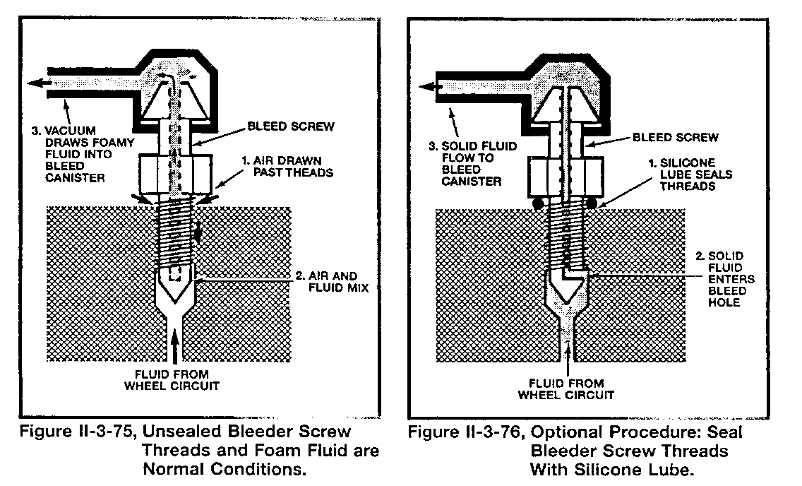
It is normal to observe bubbles or foam in the vacuum hose when using the vacuum bleeder (Figure II-3-74). This air is drawn into the fluid flow from around the bleed screw threads; it has no effect on bleeding. If desired, apply a small amou of silicone lubricant to the base of the bleed screw to prevent air entry (Figure II-3-76)
4WAL Component Fastener Torque Specifications
Fastener Torque (N.m/lb. ft.)
Front wheel speed sensor mounting bolt 15 (10) Rear wheel speed sensor mounting bolt 35 (10) EHCU-to-mounting bracket bolt 25 (18) EHCU mounting bracket-to-body bolt 25 (18) EHCU hydraulic fittings: Rear inlet 20-30 (14-22) Rear outlet 20-30 (14-22) Front inlet 20-30 (14-22) Left front outlet 20-30 (14-22) Right front outlet 20-30 (14-22) EHCU air bleed screw 7 (5)
4WAL Component Part Numbers
Component GM Part Number
EHCU, M-Series truck 15649174 EHCU, S-Series truck 15649173 EHCU, L-Series truck 15649175 EHCU, T-Series truck 15649173 Left front wheel speed sensor, M-Series truck 15602572 Left front wheel speed sensor, S-Series truck 15644596 Left front wheel speed sensor, L-Series truck 15649179 Left front wheel speed sensor, T-Series truck 15644596
Component GM Part Number
Right front wheel speed sensor, M-Series truck 15602572 Right front wheel speed sensor, S-Series truck 15644596 Right front wheel speed sensor, L-Series truck 15649179 Right front wheel speed sensor, T-Series truck 15644596 Left rear wheel speed sensor, M-Series truck 15649151 Left and right rear wheel speed sensor, S-Series truck 15608698 Left rear wheel speed sensor, L-Series truck 15649151 Left rear wheel speed sensor, T-Series truck 15623837 Right rear wheel speed sensor, M-Series truck 15649152 Right rear wheel speed sensor, L-Series truck 15649152 Right rear wheel speed sensor, T-Series truck 15623837
4WAL System Diagnosis and Service Information Quick Reference Chart
Diagnosis procedures:
- Read trouble codes:
- Without Tech 1: ground ALDL terminal H (page II-3-2) - With cams: use - With Tech 1: use screen command (page II-3-8) screen command
- Clear trouble code memory:
- Without Tech 1: follow special procedure (page 11-3-2) - With cams: use - With Tech 1: use bi-directional command (page 11-3-1 1) bi-directional command - Perform function test:
- Without Tech 1: not available - With cams: use - With Tech 1: use bi-directional command (page 11-3-10) bi-directional command - Read enhanced codes:
- Without Tech 1: not available - With cams: use - With Tech 1: use screen command (page 11-3-15) screen command
- Read code histories:
- Without Tech 1: not available - With cams: use - With Tech 1: use screen command (page 11-3-14) screen command
Service procedures:
- Brake hydraulic system bleeding procedure (refer to pages II-3-47 to II-3-50)
- Without new EHCU:
Use conventional pressure or vacuum equipment Use conventional bleeding procedure
- With new EHCU:
Use conventional pressure or vacuum equipment
Follow this sequence:
- Install two HPA bleed valve depressing tools - Remove HPA bleed valve depressing tools - Loosen two air bleed screws 1/4-turn - Tighten two air bleed - Use conventional bleeding procedure screws to specified torque
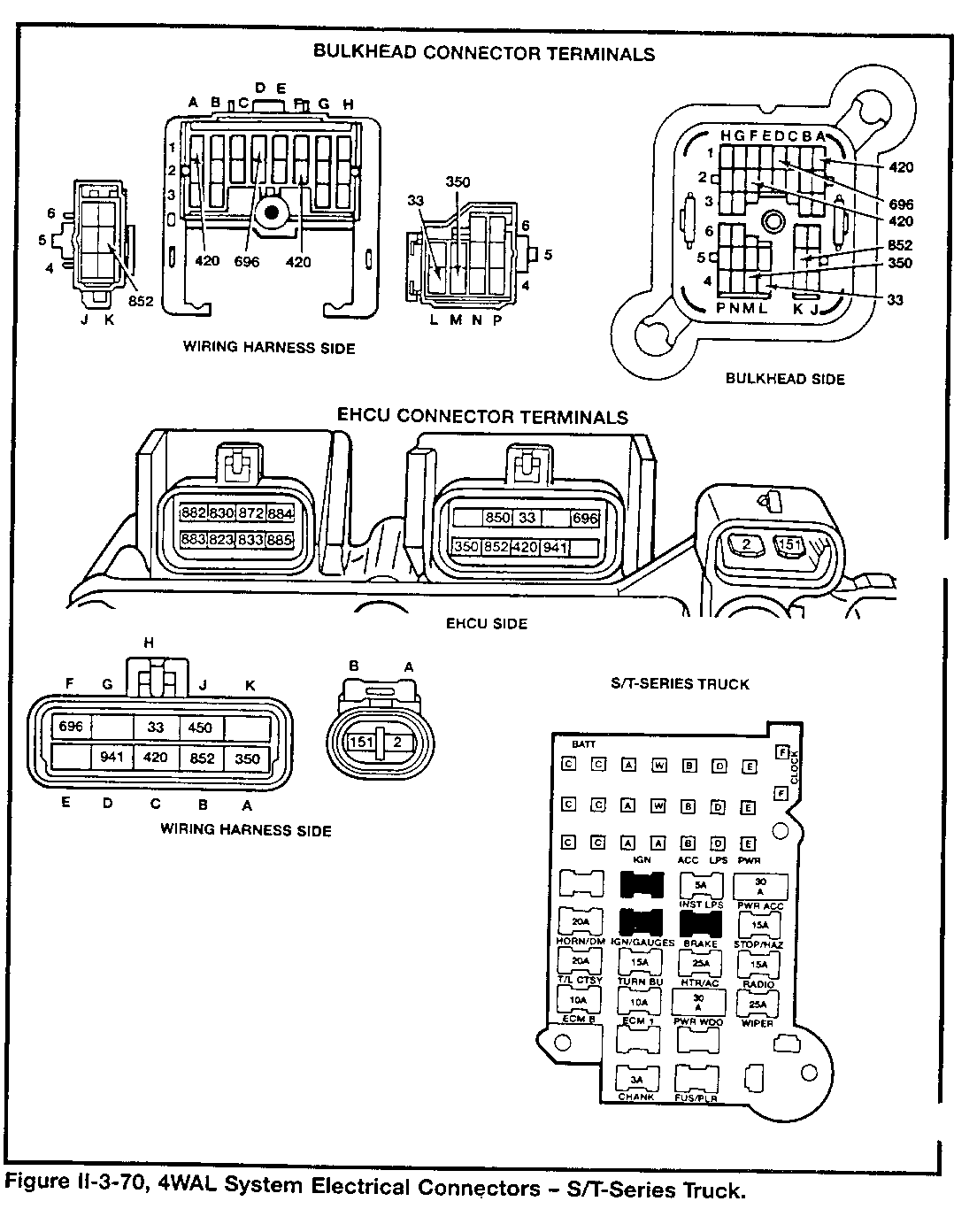
- Locating electrical circuits and in-harness diodes
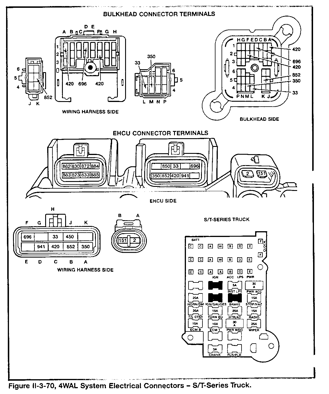
- M/L-Series truck (van): see page II-3-42 to II-3-44 - S/T-Series truck: see pages II-3-45 to II-3-46
- Following fastener torque specifications: see page II-3-50
General Motors bulletins are intended for use by professional technicians, not a "do-it-yourselfer". They are written to inform those technicians of conditions that may occur on some vehicles, or to provide information that could assist in the proper service of a vehicle. Properly trained technicians have the equipment, tools, safety instructions and know-how to do a job properly and safely. If a condition is described, do not assume that the bulletin applies to your vehicle, or that your vehicle will have that condition. See a General Motors dealer servicing your brand of General Motors vehicle for information on whether your vehicle may benefit from the information.
