SMU - SEC. 7A - TRANSMISSION UNIT REPAIR UPDATE 3-4 CLUTCH

Subject: TRANSMISSION UNIT REPAIR UPDATE 3-4 CLUTCH
Model and Year: 1987-93 CAPRICE, CAMARO AND CORVETTE 1987-93 G AND M VAN, 1987-93 C/K, RN AND S/T TRUCKS 1990-93 L VAN WITH 4L60 AND 4L60-E AUTOMATIC TRANSMISSION
BULLETIN COVERS:
New Product Information for 1993 HYDRA-MATIC 4L60 and 4L60-E transmissions. This information has been update since publication of the l993 Service Manual and should be noted accordingly. Be certain to familiarize yourself with the updates to properly repair the 1993 HYDRA-MATIC 4L60 and 4L60-E transmissions.
DATE OF PRODUCTION CHANGE:
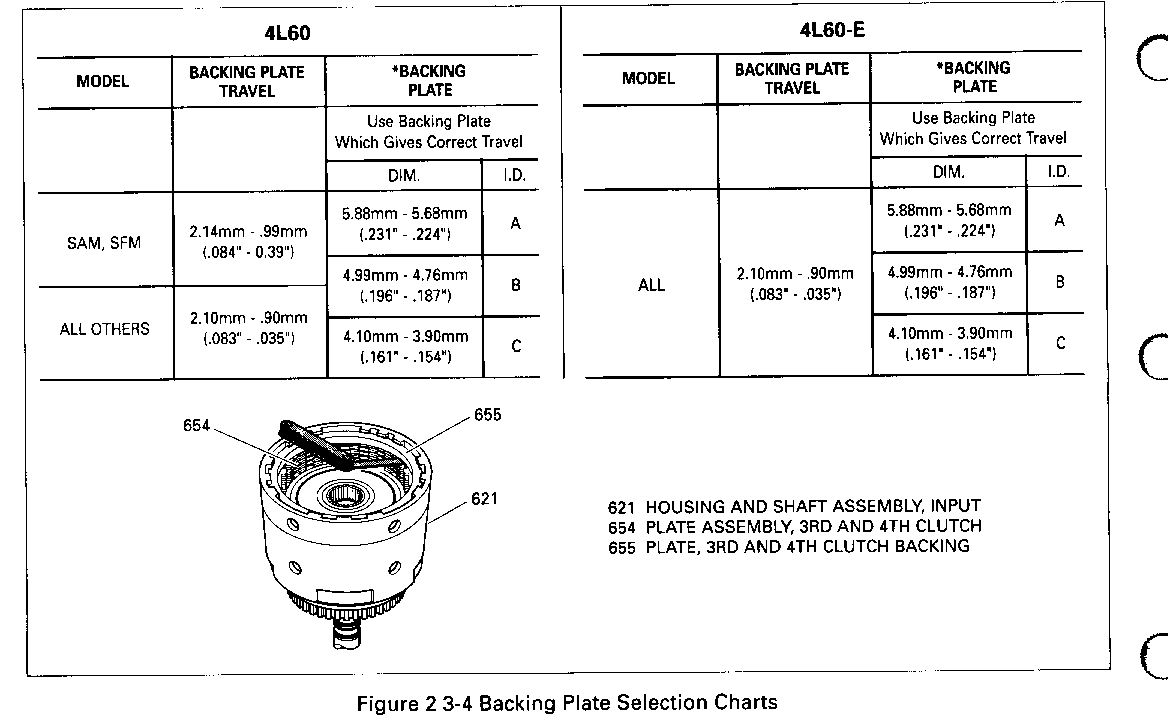
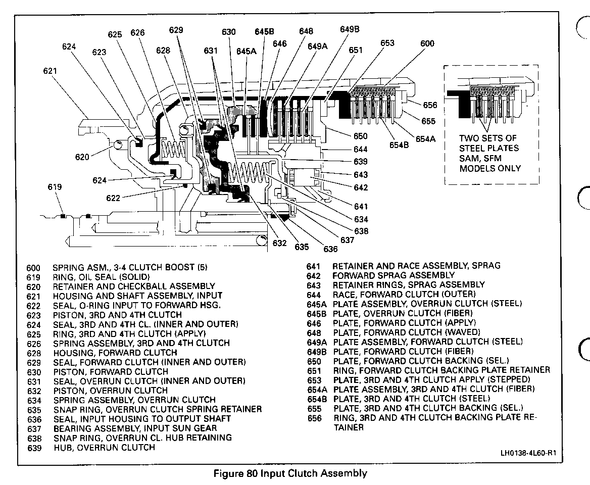
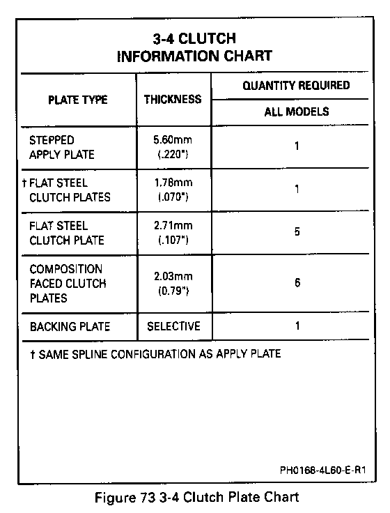
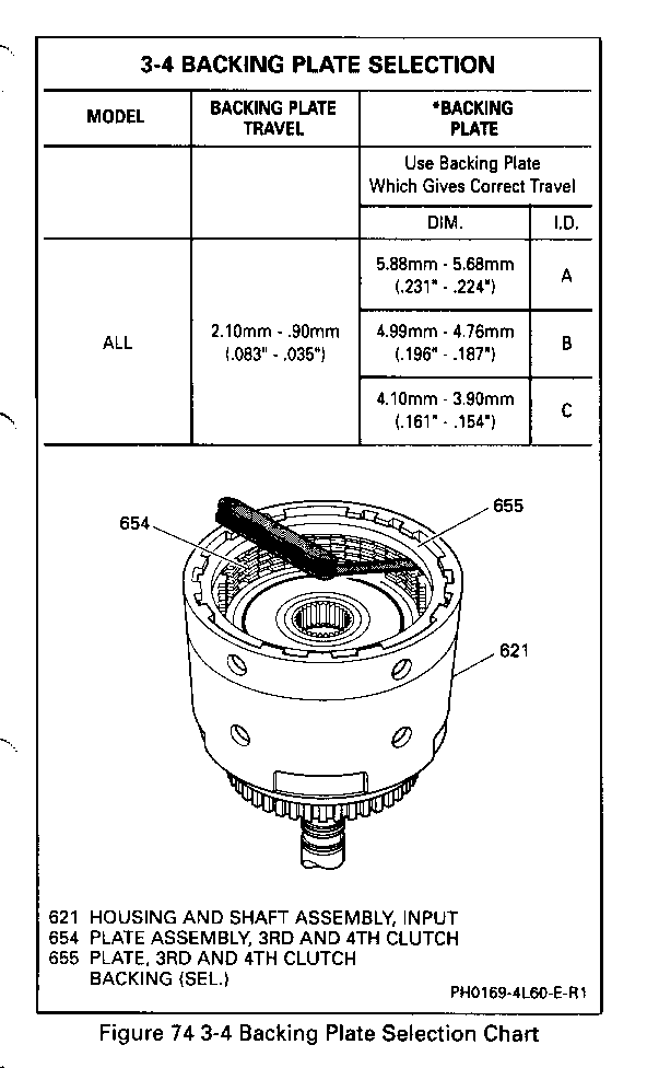
On January 05,1993 (Julian Date 005) HYDRA-MATIC 4L60 and 4L60-Etransmissions were built with an improved design 3-4 clutch. The improved design consisted of combining the 3rd and 4th clutch ring retainer plate (111. 652), the 3rd a 4th clutch apply (stepped) plate (111. 653) and the 3rd and 4th clutch (steel) plate (111. 654C) into one 3rd and 4th clutch apply plate (111. 653) Figure 1. The 3rd and 4th clutch steel plates are also thicker and the backing plate selection has changed as noted in Figure 2.
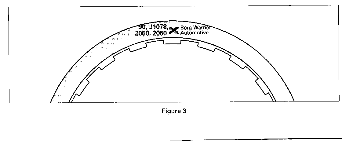
NOTE: In the overhaul repair kits for the HYDRA-MATIC 4L60 there are two (2) sets of 3rd and 4th clutch fiber plate The two 3rd and 4th clutch fiber plates are calibration sensitive and interchanging the wrong plates may cause premature failure. The following chart shows which models should use the plates labeled "2050" Figure 3.
1991 1992 1993
1AAM 2ADM 3AAM 3ADM 1APM 2AKM 3AFM 3ASM 1CNM 2BFM 3BAM 3BBM lCYM 2CHM 3BCM 3BFM 1FYM 2CJM 3BHM 3BRM 1KWM 2FUM 3BWM 3CPM 1LHM 2KJM 3FAM 3FDM 1RCM 2LHM 3FFM 3FMM 1RDM 2WCM 3LHM 3SFM lYHM 2YCM 3YAM 3YCM 2YDM 3YDM
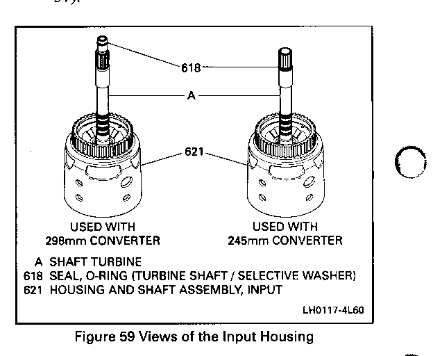
Inspect Figures 57 and 59
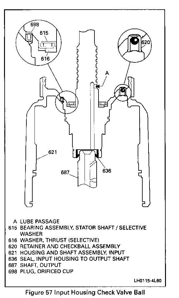
0 Turbine shaft 0-ring seal (618) for: - Damage. - Damage. 0 Input housing check valve ball (620): - The ball must move freely. - Leak check the ball with solvent.
Important
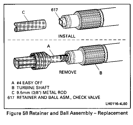
0 If the 3-4 clutch plates are burned or worn and a cause is not found during diagnosis or disassembly, replacement of the retainer and check ball assembly may be required (Figure 57).
Remove or Disconnect Figure 60 0 Tap out retainer and ball assembly.
Install or Connect Figures 58 and 60 0 Using same tools, tap in retainer and ball assembly until shoulder is seated in housing. 0 The 3-4 clutch apply plate (653) for: - Flatness. - Bent tangs. - Surface finish damage.
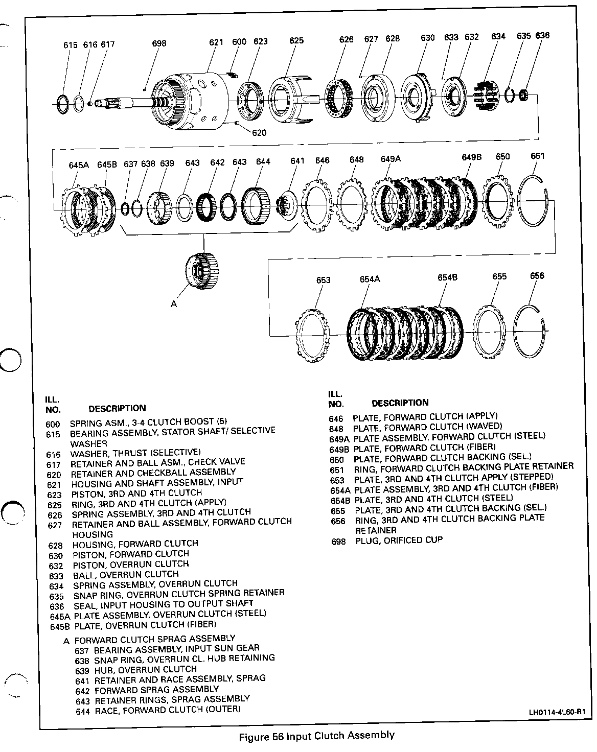
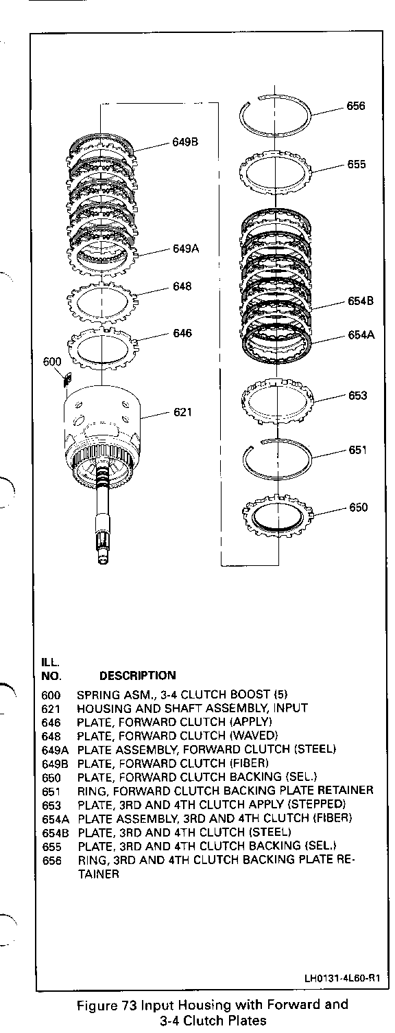
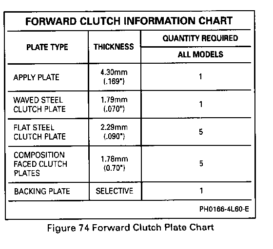
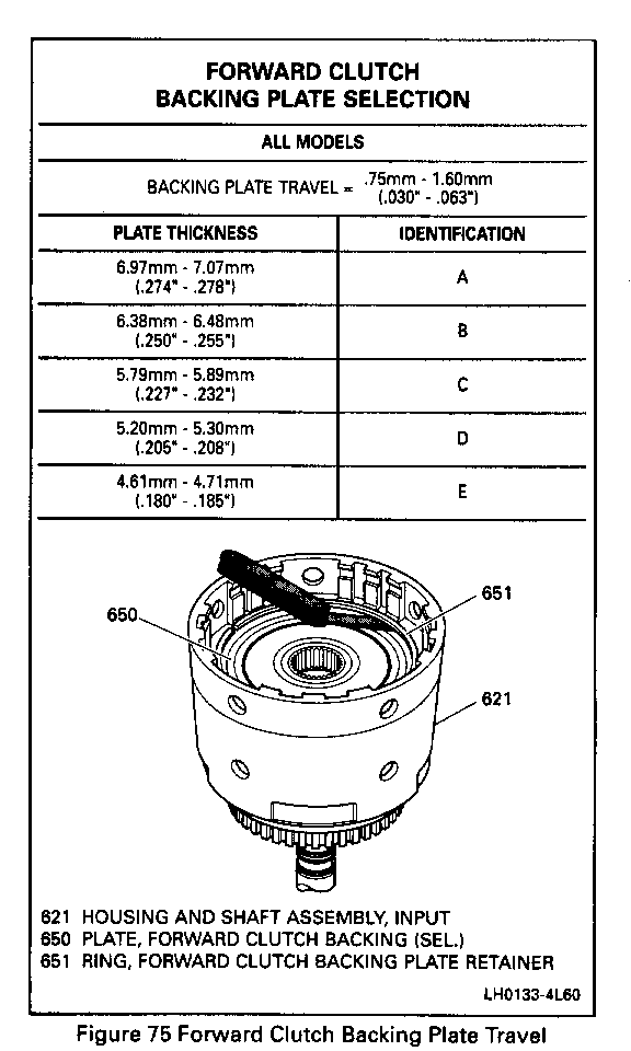
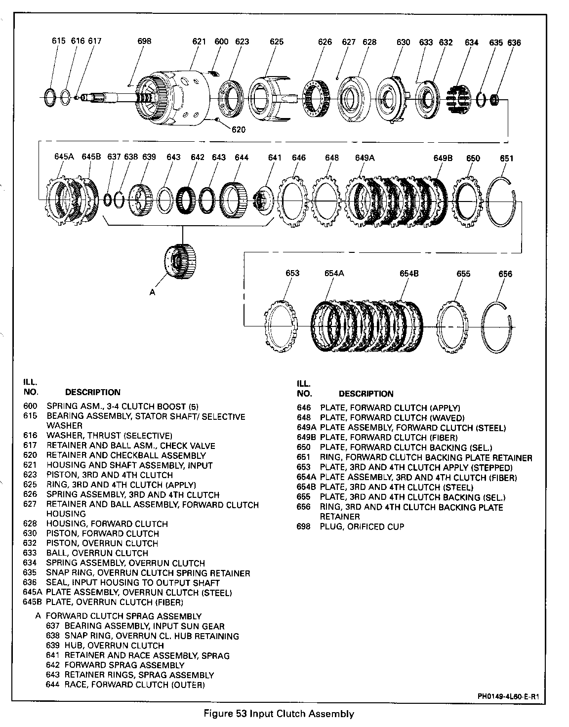
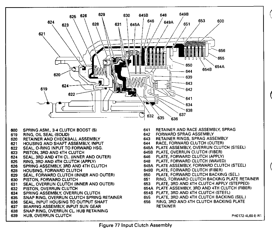
Assemble Figures 72 through 75 1 . Forward clutch apply plate (646) into the input clutch housing. 0 Index as shown. 2. Waved steel forward clutch plate (648) into the input clutch housing. 0 Index as shown. 3. The remaining forward clutch plates (649) into the input clutch housing. 0 Start with a steel plate and alternate with composition. 4. Forward clutch selective backing plate (650). 5. Forward clutch retaining ring (651).
Forward Clutch Piston Travel Check Figure 75 Measure
1. With the overrun clutch and forward clutch fully assembled in the Input Housing, check the end clearance between the backing plate (650) and the retaining ring (651) with two feeler gages. 2. Proper forward clutch backing plate travel should be 0.75 to 1.60 mm (0.030 to 0.063 inch). 3. Select the proper backing plate from the chart to obtain the correct clearance.
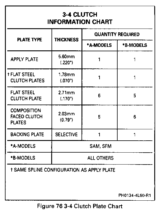
3-4 Clutch Assembly Figures 76 and 80 Assemble 1. The 3-4 clutch apply plate (653). 0 Index each leg into the apply ring legs. 2. The 3-4 clutch plates (654). 0 Start with steel and alternate with composition as shown in (Figure 80). 0 First steel plate has the same spline configuration as apply plate. 3. The 3-4 boost springs (600). 4. The 3-4 clutch backing plate (655) and retainer ring (656). 09 Chamfered side up.
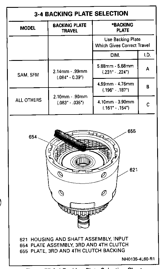
3-4 Clutch Piston Travel Check Figure 77 Measure
0 Check the end clearance between the backing plate (655) and the first composition plate with a feeler gage. 0 Select the proper backing plate from the chart to obtain the correct clearance for model you are working on.
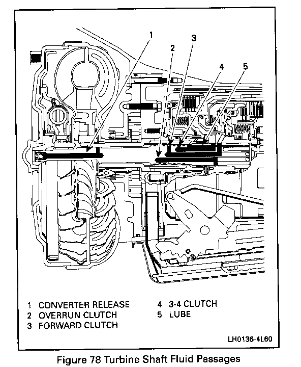
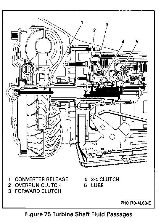
Clutch Air Check Figure 78 Air check the 3-4, forward, and overrun clutches by applying air pressure at the feed holes in the turbine shaft. (When the overrun clutch is checked, the air will blow by the forward clutch piston lip seals and exit out the forward clutch feed hole in the turbine shaft.)
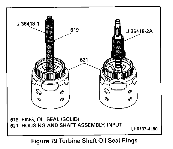
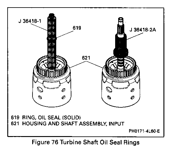
Turbine Shaft Seals Figure 79 Tools Required: J 36418-1 Seal Installer J 364l8-2A Seal Sizer
Assemble 1. Install four turbine shaft oil seal rings (619) using J-36418-1.
Adjust o Adjust screw to obtain proper height. 2. Use J 364l8-2A to size the seals after installation.
Reverse Input Clutch Assembly Figures 81 through 86 Tools Required: J 23327-1 Clutch Spring Compressor J 25018-A Clutch Spring Compressor Adaptor
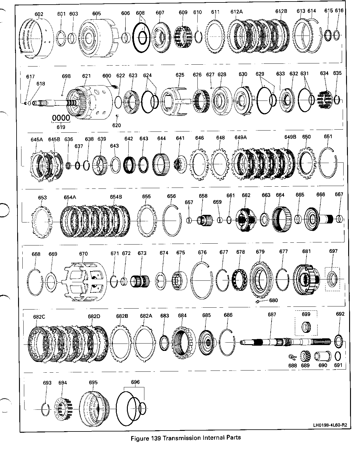
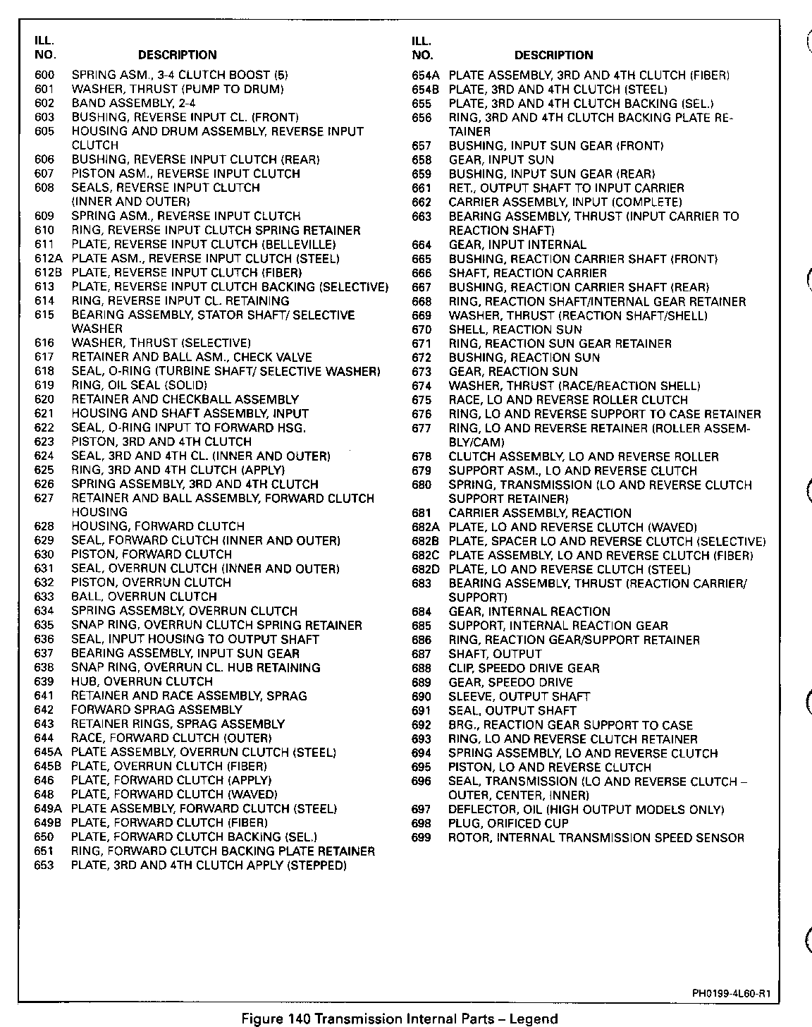
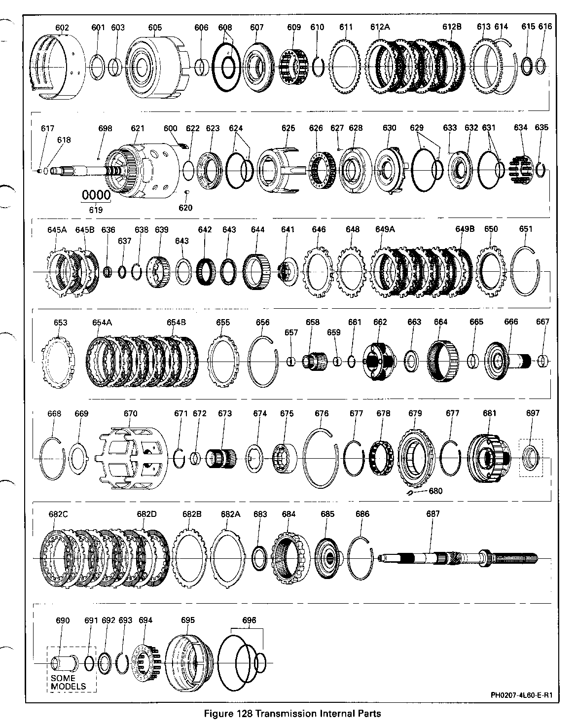
Disassemble Figures 81 and 82 1. Retaining ring (614) from reverse input housing. 2. Backing plate (613). 3. Clutch plates (612) and Belleville steel plate (611). 4. Install J 23327-1 and J 25018-A. 0 Compress the spring assembly. 5. Spring assembly retainer ring (610) and spring assembly (609). 6. Reverse input clutch piston (607). 0 Inner and outer lip seals (608).
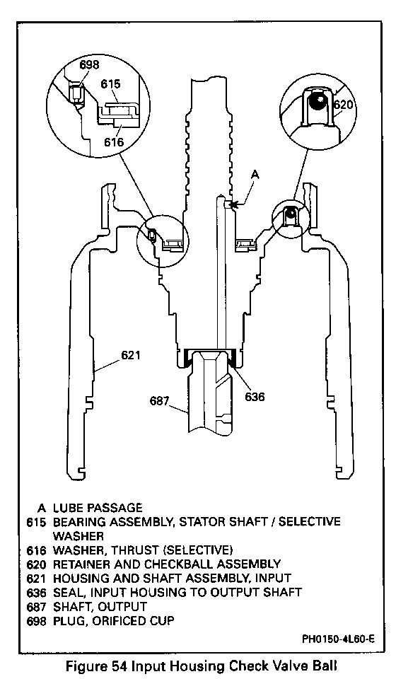
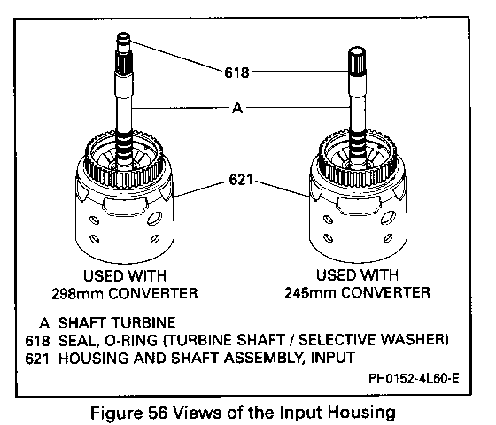
Inspect Figures 54 and 56 0 Turbine shaft 0-ring seal (618) for: - Damage. - Nicks or cuts. 0 Input housing check valve ball (620): - The ball must move freely. - Leak check the ball with solvent.
Important
0 If the 3-4 clutch plates are burned or worn and a cause is not found during diagnosis or disassembly, replacement of the retainer and checkball assembly may be required (Figure 54).
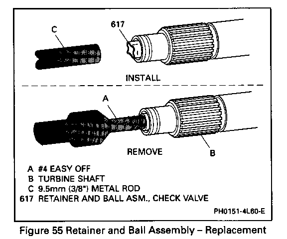
Remove or Disconnect Figure 57 0 Tap out retainer and ball assembly.
Install or Connect Figures 55 and 57 0 Using same tools, tap in retainer and ball assembly until shoulder is seated in housing. 0 The 3-4 clutch apply plate (653) for: - Flatness. - Bent tangs. - Surface finish damage.
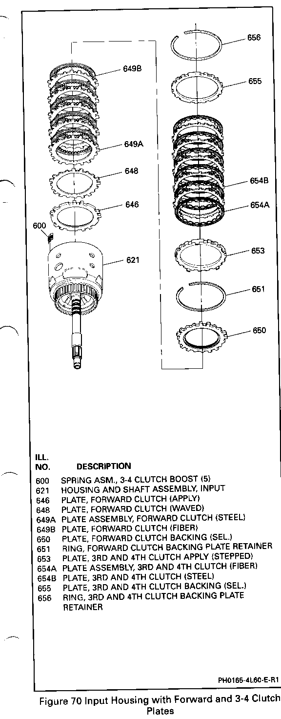
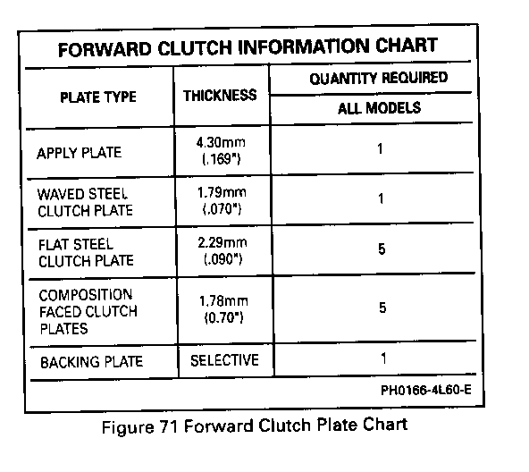
Assemble Figures 69 through 72 1. Forward clutch apply plate (646) into the input clutch housing. 0 Index as shown. 2. Waved steel forward clutch plate (648) into the input clutch housing. 0 Index as shown. 3. The remaining forward clutch plates (649) into the input clutch housing. 0 Start with a steel plate and alternate with composition. 4. Forward clutch selective backing plate (650). 5. Forward clutch retaining ring (651).
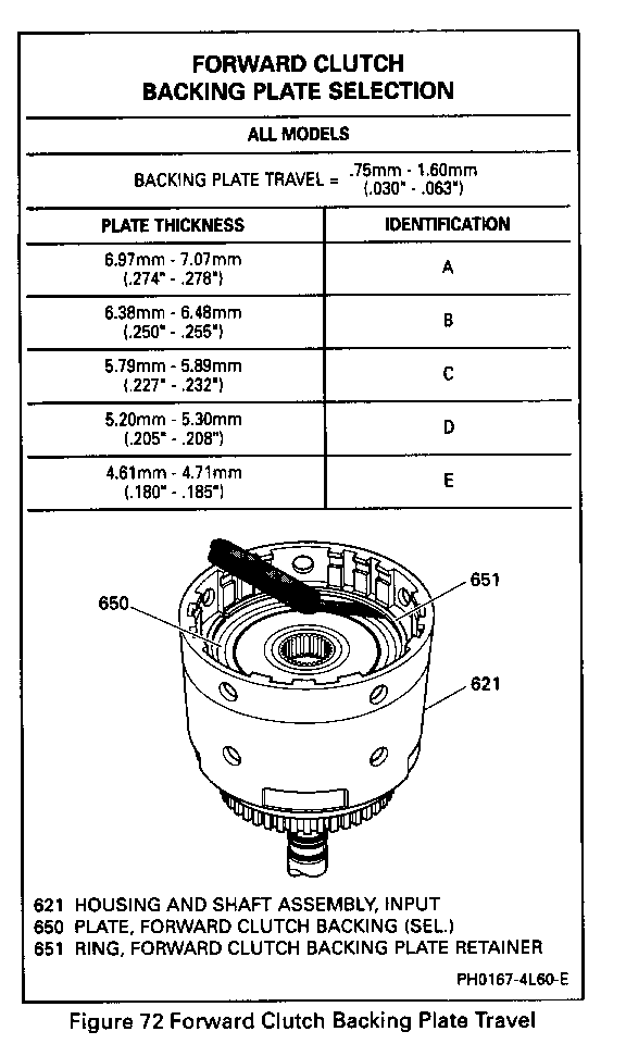
Forward Clutch Piston Travel Check Figure 72 Measure 1. With the overrun clutch and forward clutch fully assembled in the Input Housing, check the end clearance between the backing plate (650) and the retaining ring (651) with two feeler gages. 2. Proper forward clutch backing plate travel should be 0.75 to 1.60 mm (0.030 to 0.063 inch). 3. Select the proper backing plate from the chart to obtain the correct clearance.
3-4 Clutch Assembly Figures 73 and 77 Assemble 1. The 3-4 clutch apply plate (653). 0 Index each leg into the apply ring legs. 2. The 3-4 clutch plates (654). 0 Start with steel and alternate with composition as shown in (Figure 77). 0 First steel plate has the same spline configuration as apply plate. 3. The 3-4 boost springs (600). 4. The 3-4 clutch backing plate (655) and retainer ring (656). 0 Chamfered side up.
3-4 Clutch Piston Travel Check Figure 74 Measure 0 Check the end clearance between the backing plate (655) and the first composition plate with a feeler gage. 0 Select the proper backing plate from the chart to obtain the correct clearance for model you are working on.
Clutch Air Check Figure 75 Air check the 3-4, forward and overrun clutches by applying air pressure at the feed holes in the turbine shaft. (When the overrun clutch is checked, the air will blow by the forward clutch piston lip seals and exit out the forward clutch feed hole in the turbine shaft.)
Turbine Shaft Seals Figure 76 Tools Required: J 36418-1 Seal Installer J 364l8-2A Seal Sizer
Assemble 1. Install four turbine shaft oil seal rings (619) using J-36418-1.
Adjust o Adjust screw to obtain proper height. 2. Use J 364l8-2A to size the seals after installation.
Reverse Input Clutch Assembly Figures 78 through 83 Tools Required: J 23327-1 Clutch Spring Compressor J 25018-A Clutch Spring Compressor Adaptor
Disassemble Figures 78 and 79 1. Retaining ring (614) from reverse input housing. 2. Backing plate (613). 3. Clutch plates (612) and Belleville steel plate (611). 4. Install J 23327-1 and J 25018-A. 0 Compress the spring assembly. 5. Spring assembly retainer ring (610) and spring assembly (609). 6. Reverse input clutch piston (607). 0 Inner and outer lip seals (608).

General Motors bulletins are intended for use by professional technicians, not a "do-it-yourselfer". They are written to inform those technicians of conditions that may occur on some vehicles, or to provide information that could assist in the proper service of a vehicle. Properly trained technicians have the equipment, tools, safety instructions and know-how to do a job properly and safely. If a condition is described, do not assume that the bulletin applies to your vehicle, or that your vehicle will have that condition. See a General Motors dealer servicing your brand of General Motors vehicle for information on whether your vehicle may benefit from the information.
