Perform the following test using the control assembly in order to determine whether the following are working properly:
| • | The electrical system |
| • | The vacuum system |
| • | The refrigeration system |
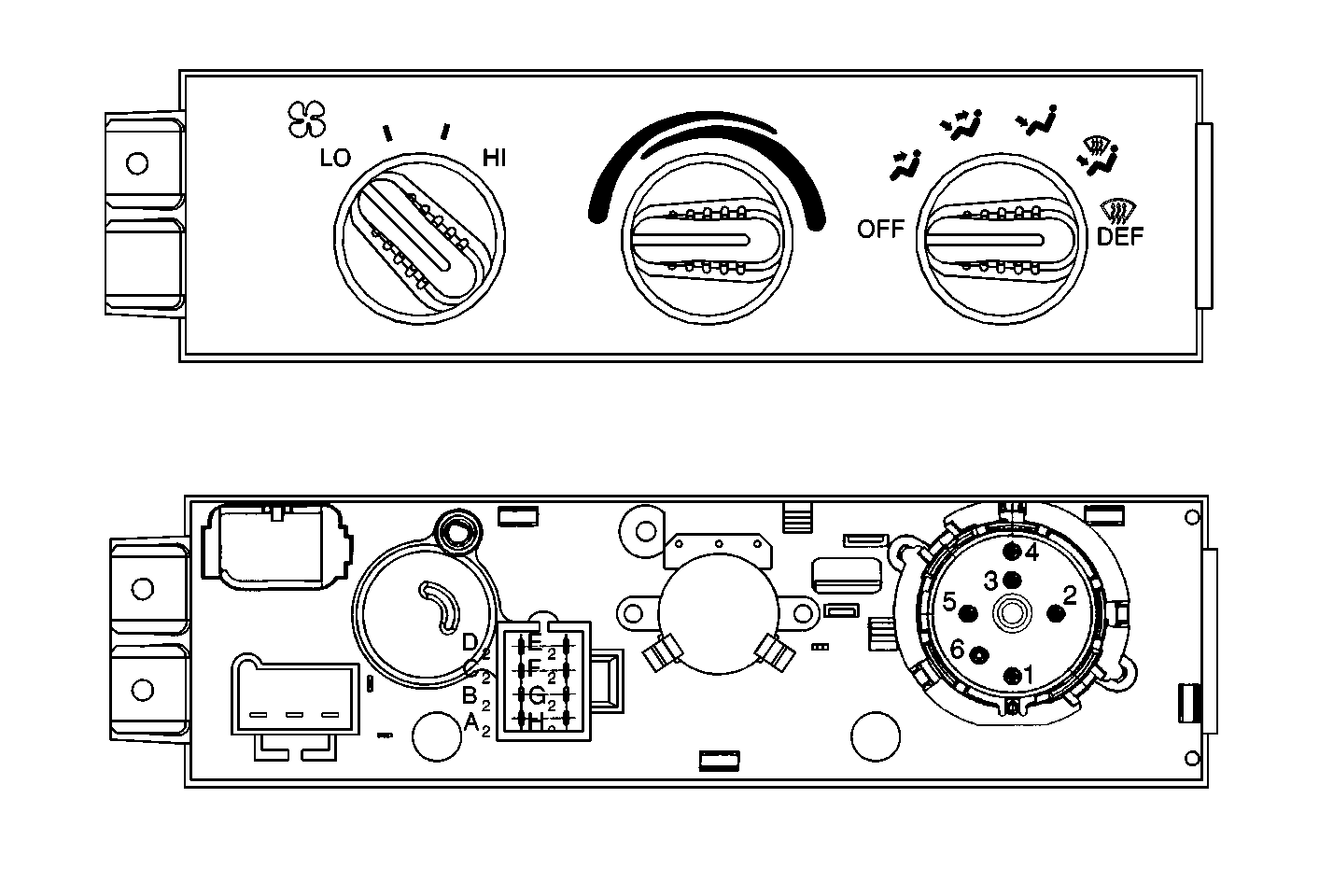
- Check the blower speed from the LOW to the HIGH range in order to verify the proper operation of the following components:
- Test each mode to verify the proper function of the following systems:
- Verify that each of the modes responds as follows:
- Test the temperature selector functions as follows:
| • | The blower switch |
| • | The blower motor |
| • | The blower resistor |
| • | The high blower relay |
| • | Proper air flow distribution |
| • | Correct function of the vacuum connections and their associated parts |
| • | Correct function of the complete electrical system, including the following: |
| • | The electrical actuators |
| • | The temperature sensors |
| • | The electrical connections and associated parts |
| 3.1. | The Max A/C Mode: |
| • | Air flow from the A/C outlets, including the lap air outlets |
| • | The recirculation door opens |
| • | The blower motor sounds louder than in the Normal A/C mode |
| • | The A/C compressor operates |
| 3.2. | The Normal A/C Mode: |
| • | Air flow from the A/C outlets, including the lap air outlets |
| • | The recirculation door closes |
| • | The A/C compressor operates |
| 3.3. | The Bi-Level A/C Mode: |
| • | Air flow from the A/C outlets, including the lap air and heater outlets |
| • | The A/C compressor operates |
| 3.4. | The Vent Mode: |
| • | Air flow from the A/C outlets, including the lap air outlets |
| • | The A/C compressor does not operate |
| 3.5. | The Heater Mode |
| • | Air flow from the heater outlets |
| • | A small amount of air flow from the defroster outlet and the side window defoggers |
| 3.6. | The Blend Mode: |
| • | Air flow from the defroster outlet |
| • | Air flow from the side window defoggers and the heater outlet. |
| • | The A/C compressor does not operate |
| 3.7. | The Defrost Mode |
| • | Air flow from the defroster outlet |
| • | Air flow from the side window defoggers |
| • | A small amount of air flow from the heater outlets. |
| • | The A/C compressor may operate |
| 4.1. | Check the temperature knob effort by moving the knob from the BLUE (cold) zone, to the RED (hot) zone. |
| 4.2. | Listen for the valve seating in the full BLUE (cold) zone and the full RED (hot) zone. |
| 4.3. | Check for heated air by placing the temperature knob in the full RED (hot) zone and the mode knob in the DEFROST position. |
| 4.4. | Check for cooled air by placing the temperature knob in the full BLUE (cold) position and the mode knob in the MAX A/C or the NORM A/C positions. |
Note the temperature of the air from the outlets. After one minute of operation, the air from the A/C outlets should be at least -7°C (20°F) below the ambient air temperature.
Checking the temperature range verifies the proper function of the following:
| • | All vacuum, electrical, and refrigerant system connections |
| • | All heater system connections |
| • | The temperature door in the heater assembly |
| • | The temperature knob for temperature selection |
Performance Test
Tools Required
J 21213-A Four Jack-Dual Range Temperature Tester
- Park the vehicle inside, or in a shaded area.
- Open the doors or the windows to ventilate the interior.
- Vent the engine exhaust, if necessary.
- Open the hood and install high and low-side pressure gauges.
- Close the hood.
- Record the ambient temperature at the vehicle.
- Record the relative humidity.
- Close the doors or windows.
- Set the controls as follows:
- Open the air conditioning outlets.
- Install the J 21213-A
- Place the transmission in PARK or NEUTRAL.
- Start the engine speed.
- Run the air conditioning system until the outlet air reaches the lowest temperature (about 3 minutes).
- Record the following:
- Turn the engine off and compare the readings.
- If a malfunction is suspected due to abnormal system pressures, inspect the system for the following:
- If the problem is not found, refer to C.C.O.T. Air Conditioning Diagnosis.
Route the lines over the rear hood seal, and tape the gauges to the windshield for viewing.
Use a psychrometer to measure atmospheric moisture or consult the local weather bureau.
Important: Be sure to record the relative humidity and ambient temperature at the time of the test.
| • | Set the mode knob to NORMAL A/C. |
| • | Set the blower switch on HIGH. |
| • | Set the temperature knob fully on BLUE (cold). |
Stabilize the engine speed at 2000 RPM and start the timer.
| • | The outlet air temperature |
| • | The high-side pressure |
| • | The low-side pressure |
Air conditioning systems that are functioning normally should not exceed the levels shown on the Pressure Temperature Relationship and System Performance Test Tables.
| 17.1. | Dirt, leaves, or other foreign material on the outer surfaces of the radiator and the condenser, or between the radiator and the condenser--These materials may be blocking the air flow. |
| 17.2. | Restrictions or kinks in the evaporator core, condenser core, hoses, tubes, etc. |
| 17.3. | Refrigerant leaks |
| 17.4. | Leaks or restrictions in air ducts--A low airflow rate may indicate a restricted evaporator core. |
| 17.5. | Slippage in the compressor clutch |
| 17.6. | Improper tension of the drive belt |
| 17.7. | Plugging of the accumulator |
| 17.8. | Plugging of the (orifice) tube |
Relative Humidity | Ambient Air Temperature | Maximum Low Side Pressure | Engine Speed | Maximum Center Air Outlet Temperature | Maximum High Side Pressure |
|---|---|---|---|---|---|
40% | 26.7°C (80°F) | 220 kPa (32 psi) | 1500 RPM | 10.6°C (51°F) | 1 572 kPa (228 psi) |
26.7°C (90°F) | 268 kPa (39 psi) | 10.6°C 59°F | 1 931 kPa (280 psi) | ||
37.8°C (100°F) | 308 kPa (44 psi) | 18.9°C (66°F) | 2 075 kPa 301 psi | ||
43.3°C (110°F) | 317 kPa (46 psi) | 23.9°C (75°F) | 2 255 kPa (327 psi) | ||
48.9°C¹ (120°F)¹ | 310 kPa¹ (45 psi)¹ | 17.2°C¹ (63°F)¹ | 2 530 kPa¹ (367 psi)¹ | ||
50% | 21.1°C² (70°F)² | 193 kPa² (28 psi)² | 6.1°C² (43°F)² | 1 103 kPa² (160°F)² | |
70% | 21.1°C (70°F) | 234 kPa (34 psi) | 12.2°C (54°F) | 1 572 kPa (228 psi) | |
32.2°C (90°F) | 324 kPa (47 psi) | 18.3°C (65°F) | 2 006 kPa 291 psi | ||
80% | 26.7°C (80°F) | 268 kPa 39 psi | 14.4°C 58°F) | 1 731 kPa (251 psi) | |
¹Determine in MAX A/C with all of the windows closed. ²The compressor cycles ON and OFF. | |||||
