Removal Procedure
Tools Required
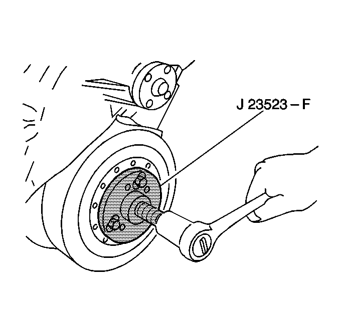
J 23523-F Crankshaft Balancer Remover
- Disconnect the battery negative cable. Refer to Battery Replacement in Engine Electrical.
- Remove the upper and lower fan shroud assembly.
- Remove the drive belt. Refer to Drive Belt Replacement .
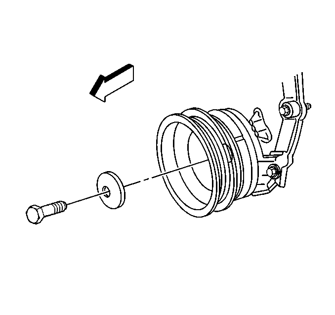
- Remove the crankshaft balancer bolt.
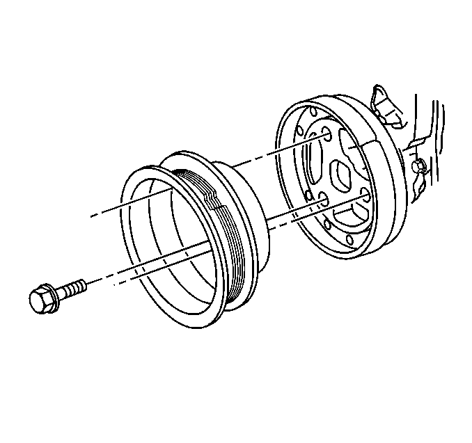
- Remove the crankshaft pulley bolts.
- Remove the crankshaft pulley.
- Use J 23523-F to remove the crankshaft balancer . Refer to Crankshaft Balancer Removal .
- Clean and inspect all parts. Refer to Crankshaft Balancer Clean and Inspect .

| • | Refer to Engine Coolant Fan Upper Shroud Replacement in Engine Cooling. |
| • | Refer to Engine Coolant Fan Lower Shroud Replacement in Engine Cooling. |


Notice: To prevent damage to the end of the crankshaft when using a crankshaft balancer removal tool install a bolt in the crankshaft. Use a shorter bolt with the same threads as the crankshaft balancer bolt. This bolt will allow a place for the tool to push against. The shorter bolt is to keep from going past the threads in the crankshaft and damaging the crankshaft threads.
Installation Procedure
Tools Required
J 23523-F Balancer Remover and Installer
- Use J 23523-F to install the crankshaft balancer. Refer to Crankshaft Balancer Installation .
- Install the crankshaft pulley.
- Loosely install the crankshaft pulley bolts.
- Install the crankshaft balancer bolt.
- Tighten the crankshaft balancer bolt to 95 N·m (70 lb ft).
- Tighten the crankshaft pulley bolts to 58 N·m (43 lb ft).
- Install the drive belt. Refer to Drive Belt Replacement .
- Install the upper and lower fan shroud assembly.
- Connect the battery negative cable. Refer to Battery Replacement in Engine Electrical.


Notice: Use the correct fastener in the correct location. Replacement fasteners must be the correct part number for that application. Fasteners requiring replacement or fasteners requiring the use of thread locking compound or sealant are identified in the service procedure. Do not use paints, lubricants, or corrosion inhibitors on fasteners or fastener joint surfaces unless specified. These coatings affect fastener torque and joint clamping force and may damage the fastener. Use the correct tightening sequence and specifications when installing fasteners in order to avoid damage to parts and systems.
Tighten
| • | Refer to Engine Coolant Fan Upper Shroud Replacement . |
| • | Refer to Engine Coolant Fan Lower Shroud Replacement . |
