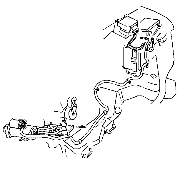
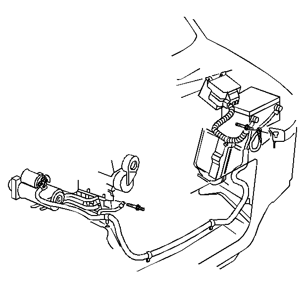
Excessive resistance caused by poor terminal connections and partial short circuits through worn cable insulation will result in an abnormal voltage drop in the starter cable. Low voltage at the starter will prevent the normal starter operation and cause hard starting.
Whenever the battery cables are replaced, use a replacement cable that is the same in the type, the diameter, and the length. Some positive cables have additional feed wires attached to them and some of the negative cables have additional ground leads attached.
Inspection Procedure
Tools Required
J 39200 Digital Multimeter
Caution: In order to prevent possible personal injury from a moving vehicle or
from an operating engine, perform the following steps before performing the
checks:
- Check the voltage drop between the ground (the battery negative terminal) and the vehicle frame.
- Check the voltage drop between the battery positive terminal and the starter terminal stud with the starter operating.
- Check the voltage drop between the starter housing and the frame with the starter operating.
- If the voltage drop in any of the above is more than 0.5 volts, there is excessive resistance in the circuit.
Place one probe of the J 39200 on the grounded battery post (not on the cable clamp) and the other on the frame.
Operate the starter and note the voltage reading.
In order to eliminate resistance, the cables should be disconnected and the connections should be cleaned.
If the cables are frayed or the clamps are corroded, the cables should be replaced.
When selecting the new cables, ensure that the new cables are the same length and the same diameter as the original cables being replaced.
Removal Procedure
Battery Negative Cable
- Disconnect the battery negative cable bolt from the battery.
- Disconnect the battery negative cable from the engine.
- Disconnect any additional ground leads attached to the battery negative cable.
- Remove the battery negative cable.
Caution: Unless directed otherwise, the ignition and start switch must be in the OFF or LOCK position, and all electrical loads must be OFF before servicing any electrical component. Disconnect the negative battery cable to prevent an electrical spark should a tool or equipment come in contact with an exposed electrical terminal. Failure to follow these precautions may result in personal injury and/or damage to the vehicle or its components.
Battery Positive Cable
- Disconnect the battery positive cable bolt from the battery.
- Disconnect the battery positive cable from the starter motor.
- Disconnect the additional battery positive cable lead to the electrical convenience center.
- Remove the battery positive cable.
Caution: Unless directed otherwise, the ignition and start switch must be in the OFF or LOCK position, and all electrical loads must be OFF before servicing any electrical component. Disconnect the negative battery cable to prevent an electrical spark should a tool or equipment come in contact with an exposed electrical terminal. Failure to follow these precautions may result in personal injury and/or damage to the vehicle or its components.
Installation Procedure
Battery Negative Cable
- For RWD, install the battery negative cable in the same position as the original.
- For A4WD, install the battery negative cable in the same position as the original.
- Connect the battery negative cable to the engine.
- Install the engine harness to the stud.
- Connect the battery negative cable ground lead to the radiator support.
- Connect the battery negative terminal bolt to the battery.


Notice: Use the correct fastener in the correct location. Replacement fasteners must be the correct part number for that application. Fasteners requiring replacement or fasteners requiring the use of thread locking compound or sealant are identified in the service procedure. Do not use paints, lubricants, or corrosion inhibitors on fasteners or fastener joint surfaces unless specified. These coatings affect fastener torque and joint clamping force and may damage the fastener. Use the correct tightening sequence and specifications when installing fasteners in order to avoid damage to parts and systems.
Tighten
Tighten the nut to 40 N·m (29 lb ft).
Tighten
Tighten the nut to 25 N·m (18 lb ft).
Tighten
Tighten the stud to 45 N·m (33 lb ft).
Tighten
Tighten the bolt to 15 N·m (11 lb ft).
Battery Positive Cable
- For RWD, install the battery positive cable in the same position as the original.
- For A4WD, install the battery positive cable in the same position as the original.
- Connect the battery positive cable to the starter solenoid.
- Connect the additional battery positive cable lead to the underhood electrical center.
- Connect the battery positive terminal bolt to the battery.


Notice: When installing the positive battery cable to the starter solenoid, the inner nut on the solenoid battery terminal must be tightened before the battery cable and the other leads are installed. Failure to do so will result in the solenoid or the solenoid terminal damage.
Notice: Use the correct fastener in the correct location. Replacement fasteners must be the correct part number for that application. Fasteners requiring replacement or fasteners requiring the use of thread locking compound or sealant are identified in the service procedure. Do not use paints, lubricants, or corrosion inhibitors on fasteners or fastener joint surfaces unless specified. These coatings affect fastener torque and joint clamping force and may damage the fastener. Use the correct tightening sequence and specifications when installing fasteners in order to avoid damage to parts and systems.
Tighten
Tighten the nut to 9 N·m (80 lb in).
Tighten
Tighten the nut to 9 N·m (80 lb in).
Tighten
Tighten the bolt to 15 N·m (11 lb ft).
