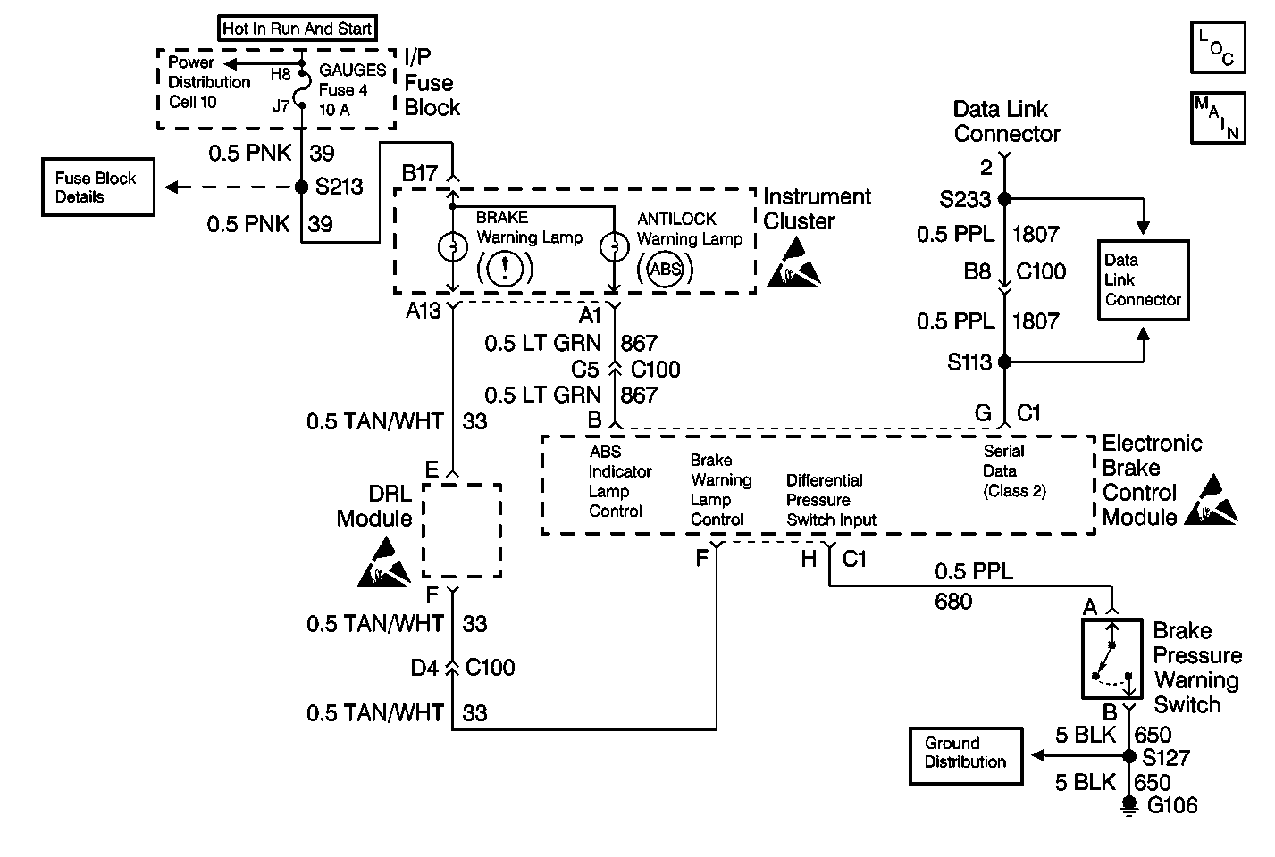
Circuit Description
The amber ABS indicator lamp is supplied ignition voltage through the GAUGES fuse. The output of the EBCM will be high (battery voltage) when the ABS indicator lamp is off, and will be low (ground) when the ABS indicator lamp is on. If a DTC C0286 sets, the EBCM will store the DTC in memory but will not disable the ABS. If a DTC C0286 is in memory and a different DTC sets which also requires the ABS indicator lamp to turn on, the EBCM will turn on the red BRAKE warning lamp to notify the driver of the problem.
Conditions for Setting the DTC
| • | High voltage is present on the ABS indicator lamp control circuit when low voltage is expected (lamp is turned on) |
| • | Anything that keeps the ABS indicator lamp circuit high when the lamp is expected to be on |
Action Taken When the DTC Sets
| • | The ABS is not disabled. |
| • | The EBCM will use the red BRAKE warning lamp to alert the driver of an ABS malfunction. |
Conditions for Clearing the DTC
| • | Repair the conditions responsible for setting the DTC |
| • | Use the Scan Tool Clear DTCs function. |
Diagnostic Aids
DTC C0286 typically sets because of a shorted ABS indicator lamp. Yet DTC C0286 can also set because of a short to voltage in the wiring between the ABS indicator lamp and the EBCM.
Test Description
The numbers below refer to the steps in the diagnostic table:
-
This step checks for normal operation of the ABS indicator lamp.
-
This step turns off the ABS indicator lamp with a J 36169-A .
Step | Action | Value(s) | Yes | No |
|---|---|---|---|---|
1 | Was the Diagnostic System Check performed? | -- | Go to Step 2 | |
| -- | Go to Step 5 | Go to Step 3 | |
Does the J 39200 indicate that a voltage is present? | -- | Go to Step 4 | Go to Step 6 | |
4 |
Does the J 39200 indicate that a voltage is present? | -- | Go to Step 7 | Go to Step 8 |
5 | Malfunction is intermittent. Inspect all connectors and harnesses for damage which may result in high resistance when all components are connected. Perform all necessary repairs. Is repair complete? | -- | Malfunction is intermittent. Go to Diagnostic Aids | |
6 | Replace the EBCM. Refer to Electronic Brake Control Module Replacement . Is repair complete? | -- | -- | |
7 | Repair a short to voltage in CKT 867. Is the repair complete? | -- | -- | |
8 | Replace the instrument cluster. Refer to Instrument Cluster Replacement . Is repair complete? | -- | -- |
