Caution: Be careful when you handle a sensor. Do not strike or jolt a sensor.
Before applying power to a sensor:
• Remove any dirt, grease, etc. from the mounting surface. • Position the sensor horizontally on the mounting surface. • Point the arrow on the sensor toward the front of the vehicle. • Tighten all of the sensor fasteners and sensor bracket fasteners
to the specified torque value.
Removal Procedure
- Disable the SIR system. Refer to Disabling the SIR System .
- Disconnect the electrical connectors from the MAF and the IAT sensors.
- Loosen the clamp.
- Remove the air tube from the throttle body air intake cover.
- Remove the bolts.
- Remove the upper radiator shroud. Refer to Engine Coolant Fan Upper Shroud Replacement in Engine Cooling.
- Remove the fan and clutch assembly. Refer to Fan Replacement in Engine Cooling.
- Remove the lower radiator shroud. Refer to Engine Coolant Fan Lower Shroud Replacement in Engine Cooling.
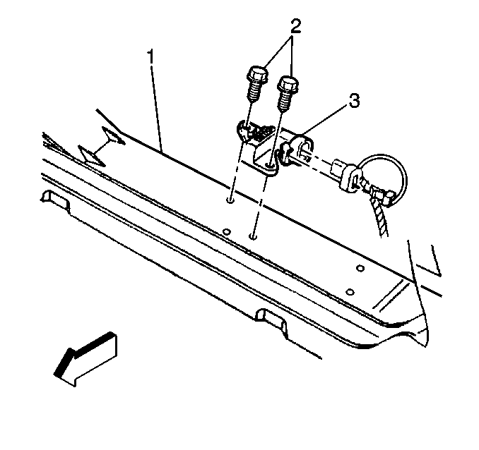
- Disconnect the electrical connector from the SIR sensor at the top of the cradle (1).
- Remove the bolts (2).
- Remove the SIR sensor (3) from the cradle.
- Perform the following steps in order to complete the first fastener repair:
- Perform the following steps in order to complete the second fastener repair:

Important: The following procedures should be utilized in the event that sensor mounting holes or fasteners are damaged to the extent that the sensor may no longer be properly mounted.
| 12.1. | Remove and discard the improperly installed rivet. |
| 12.2. | Reattach sensor with new rivet (GM P/N 15715058) or equivalent. |
| 13.1. | Remove the improperly installed rivet. |
| 13.2. | Enlarge the mounting holes in the lower radiator support to 9.0 mm (0.35 in). |
| 13.3. | Insert and properly seat rivnut (GM P/N 15699834) or equivalent. |
Notice: Use the correct fastener in the correct location. Replacement fasteners must be the correct part number for that application. Fasteners requiring replacement or fasteners requiring the use of thread locking compound or sealant are identified in the service procedure. Do not use paints, lubricants, or corrosion inhibitors on fasteners or fastener joint surfaces unless specified. These coatings affect fastener torque and joint clamping force and may damage the fastener. Use the correct tightening sequence and specifications when installing fasteners in order to avoid damage to parts and systems.
| 13.4. | Install sensor with screw (GM P/N 11515664) or equivalent. |
Tighten
Tighten fasteners to 8.0 N·m (71 lb in).
Installation Procedure
- Install the SIR sensor to the top of the cradle.
- Install the inflatable restraint front end discriminating sensor mounting fasteners (2).
- Connect the electrical connector to the SIR sensor.
- Install the lower radiator shroud. Refer to Engine Coolant Fan Lower Shroud Replacement in Engine Cooling.
- Install the fan and clutch assembly. Refer to Fan Replacement in Engine Cooling.
- Install the upper radiator shroud. Refer to Engine Coolant Fan Upper Shroud Replacement in Engine Cooling.
- Install the air box with MAF sensor to the upper radiator shroud.
- Connect the air tube to the throttle body air intake cover with the clamp.
- Connect the the electrical connectors to the MAF and IAT sensors.
- Enable the SIR system. Refer to Enabling the SIR System .

Notice: Use the correct fastener in the correct location. Replacement fasteners must be the correct part number for that application. Fasteners requiring replacement or fasteners requiring the use of thread locking compound or sealant are identified in the service procedure. Do not use paints, lubricants, or corrosion inhibitors on fasteners or fastener joint surfaces unless specified. These coatings affect fastener torque and joint clamping force and may damage the fastener. Use the correct tightening sequence and specifications when installing fasteners in order to avoid damage to parts and systems.
Tighten
Tighten fastener to 6.5 N·m (58 lb in).
