GM Service Manual Online
For 1990-2009 cars only

Second-Order Driveline Vibration Theory


Object Number: 182178  Size: SH

A faulty universal joint (U-joint) may cause a vibration that occurs twice for each rotation of the propeller shaft. This type of vibration is called a second-order vibration.

Second-order driveline vibrations are independent of runout or balance of a driveline component.

The following description of basic U-joint theory will help you to understand where second-order driveline vibrations originate and why they occur.
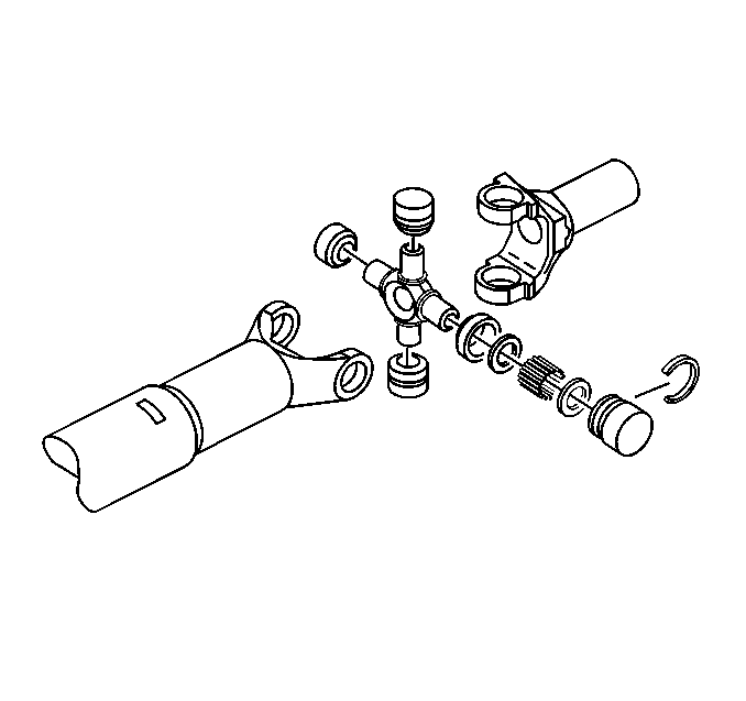
    • As the propeller shaft rotates, the U-joint speeds up and slows down twice for each rotation of the propeller shaft.
    • The acceleration and deceleration of the U-joint is not visible. If there is vibration in the U-joint, the acceleration and deceleration will be audible and tactile.
    • Compare the U-joint in a vehicle to a universal-type socket. When a universal-type socket is used to tighten a bolt, the socket will bind and release as the socket turns toward 90 degrees. The bind and release occurs twice for each revolution of the socket.
    • The U-joint in a vehicle works in the same way as the universal-type socket. The bind and release effect is directly proportional to the angle that the U-joint operates: the greater the angle, the greater the effect.
    • Because the transmission output speed is constant, the binding and releasing of the U-joint is better described as an acceleration and deceleration which occurs twice for each revolution of the propeller shaft.
    • If the propeller shaft is running slowly, the accelerating and decelerating effect is visible. The acceleration and deceleration may create a vibration due to the fluctuations in force that are generated at high speeds.

Canceled Out Driveline Angles


Object Number: 182180  Size: SH
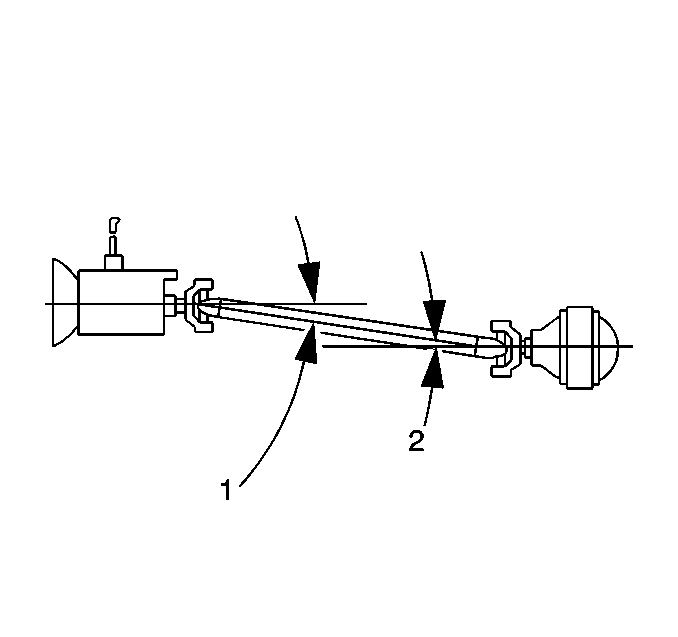
(1)Front Working Angle
(2)Rear Working Angle

Engineers design drivelines in order to compensate for the accelerations and decelerations in order to produce a smooth, constant flow of power, as listed below:

    • The transmission drives the front yoke of the propeller shaft at a smooth and constant speed.
    • The first U-joint causes the power to fluctuate twice for each revolution of the propeller shaft.
    • The second U-joint, oriented 90 degrees from the first U-joint, causes the power to fluctuate opposite that of the first U-joint.
    • As the first U-joint slows down, the second U-joint speeds up.

This design causes 1 U-joint to cancel out the effect of the other U-joint. The cancelled effects result in a smooth, constant power flow from the output yoke of the propeller shaft.

Second-order driveline vibrations occur when the cancellation becomes unequal between the front U-joint and the rear U-joint.

The main objective of this section is to correct the conditions that interfere with the proper cancellation effect of the U-joint. The most common condition, especially where the launch shudder is concerned, is incorrect driveline working angles (1,2). Other factors may aggravate the condition.

Address the following factors before you attempt to measure or correct the driveline working angles:

    • Worn, failed, damaged or improperly installed U-joint
    • Worn, collapsed, or improper powertrain mounts
    • Incorrect vehicle trim height adjustment for the front suspension which aggravates the launch shudder
    • Incorrect trim height adjustment for the rear suspension
    • Trim height inspection includes trim heights that are too low or too high. The following vehicles fit into this category:
       - Vehicles equipped with aftermarket lift kits
       - Vehicles constantly loaded with cargo
       - Custom conversion vans

On rear drive vehicles, the pinion nose tilts upward as you lower the rear trim height.

If a second-order driveline vibration exists after you correct these conditions, measure and correct the driveline angles.

If the complaint is present only with cargo in the vehicle, perform the measurements with the vehicle fully loaded. Once you correct a second-order driveline vibration with the vehicle loaded, the vibration may reappear with the vehicle unloaded. The reverse of this condition is also true. You may have to reach a compromise with the customer in this case.

Second-Order Driveline Vibration Symptoms

Second-Order driveline vibration has the following signs and symptoms:

    • The vibration is always related to vehicle speed.
    • The vibration is usually torque-sensitive.
    • The vibration is worse under a torque load.

Launch shudder is the most common complaint of a second-order driveline vibration.

Launch shudder occurs during acceleration from 0-40 km/h (0-25 mph). Launch shudder appears as a low frequency shake, wobble, or shudder. The driver may feel the vibrations in the seat or steering wheel at low speeds of 0-24 km/h (0-15 mph). The vibrations will increase in frequency as the vehicle speed increases. Launch shudder feels more like driveline roughness at higher speeds of 24-40 km/h (15-25 mph). At speeds greater than 40 km/h (25 mph) the vibration usually disappears.

Launch shudder vibration is equal to a second-order vibration of the driveline. The EVA will not perceive frequency information due to the transitory nature of launch shudder.

Driveline Working Angles

Tools Required

    • J 38460 Digital Inclinometer
    • J 23498-A Driveshaft Inclinometer
    • J 23498-20 Driveshaft Inclinometer Adapter

Object Number: 6498  Size: SH

Driveline working angle does not refer to the angle of any 1 shaft, but to the angle that is formed by the intersection of 2 shafts.

The procedure for measuring and correcting driveline working angles depends on whether the vehicle is equipped with a propeller shaft consisting of 1 piece, 2 pieces, or 3 pieces.

In order to verify the accuracy of the adapter, inspect the angle of an accessible joint with the inclinometer prior to assigning the adapter on an inaccessible joint.

One-Piece Propeller Shaft System

Raise the vehicle on a suitable hoist or on safety stands. Ensure that the rear axle is supported at curb height and that the wheels are free to spin. Refer to Lifting and Jacking the Vehicle in General Information. Place the transmission in Neutral. Ensure that the vehicle has a full tank of fuel or the equivalent amount of weight in the rear to simulate a full tank. The weight of 3.8 liters of gasoline (1 gallon) is approximately 2.8 kg (6.2 lb).

Checking Phasing of U-joint

Inspect the propeller shaft for correct phasing. Correct phasing means that the front and the rear U-joint are directly in line or parallel with each other so that proper cancellation takes place.


    Object Number: 182316  Size: SH
  1. Rotate the propeller shaft so that the propeller shaft rear U-joint bearing cap is vertical.

  2. Object Number: 182325  Size: SH
  3. Ensure that the front bearing cap is also vertical.
  4. Place the inclinometer on the propeller shaft rear U-joint bearing cap in order to ensure that both U-joints are vertical.
  5. Set the indicator line above the sight glass on 15 (the horizontal reference). Rotate the propeller shaft until the bubble centers in the sight glass. This action brings the rear U-joint to vertical.
  6. Remove the inclinometer without disturbing the setting. Leave the setting on 15.
  7. Install the inclinometer on the front U-joint. The bubble should remain centered plus or minus 3 degrees if the shaft is properly phased.

The out of phasing of the single-piece propeller shaft is very unusual. If the shaft is visibly out of place, the end yokes are welded on in the wrong position or the shaft is damaged due to twisting. In either case, replace the propeller shaft before continuing with this procedure.

Measuring the Working Angles


Object Number: 182180  Size: SH

The working angle of a U-joint is the difference between the angles formed when 2 shafts intersect. One piece propeller shaft systems have 2 working angles, the front (1) and the rear (2).

    • The 2 working angles should be equal within ½ of a degree.
    • The working angles should not exceed 4 degrees.
    • The working angles should not be equal to 0 because a 0 working angle will cause premature U-joint wear due to lack of rotation of the U-joint.
    • The angle formed by the propeller shaft and the rear axle pinion form the rear working angle (2)
    • The angle formed by the propeller shaft and the transmission output shaft form the front working angle (1)

The angles of these components are most accurately measured from the U-joint bearing caps. Verify that the bearing caps are free of corrosion or foreign material in order to ensure accurate readings. Remove any snap rings that may interfere with the correct placement of the inclinometer. Reinstall the snap rings after you take the measurements.

Take the measurements from the same side of the propeller shaft in order to maintain consistent angle measurements (either on the driver side or on the passenger side).


Object Number: 182332  Size: SH

Record the readings on a diagram like the one shown as you proceed through the measurements.

Evaluation

The 2 working angles in a one-piece propeller shaft system should be equal to within ½ of a degree for effective cancellation.

Correcting Working Angles

In order to change the working angles, shim the components up or down. Look closely at the existing angles. Use the existing angles and the shims in order to achieve the correct working angles.

Compared to horizontal or true level, the components located at the rear of the vehicle are usually lower than the components located at the front of the vehicle. This condition is called down in the rear. If a component with a down in the rear angle is shimmed up at the rear, the shim will bring the component closer to the horizontal (zero). Alternately, if a component with a down in the rear angle is shimmed down, the component will move farther from the horizontal (zero).

Rear Axle Wind-Up

Rear axle wind-up may cause launch shudder even when all of the working angles are within specifications. Rear axle wind-up occurs when heavy torque during acceleration causes the pinion nose to point upward. In order to compensate for axle wind-up, tip the pinion nose downward. Install the axle shims incrementally, performing a road test after each shim. Add shims until the road test indicates that the shudder is eliminated.

Rear Axle Shims

Wedge shims of different sizes are available through the parts' system and independent suppliers for the purpose of shimming the rear axle angle. Wedge shims are available in 2, 3, and 4 degrees.

Caution: Never attempt to shim a rear axle using anything except shims that are designed for this purpose. Failure to do so will result in the shims falling out and a loss of vehicle control and that could cause personal injury.


Object Number: 182361  Size: SH

Install the shims (5) in order to increase or decrease the angle of the rear axle pinion. Install the shims between the leaf spring (3) and the spring seat (2). Depending on the design of the suspension [leaf spring on top or underneath the axle (1)], and the direction of the desired change, install the shims with either the thick side toward the front of the vehicle or toward the rear of the vehicle.

Important: After installing the shims, ensure that the U-bolt has 2 or 3 threads above the nut. Ensure also that the center bolt, located in the spring seat, is long enough to seat in the locator hole. If these 2 conditions do not exist, use longer U-bolts and center bolts. Longer U-bolts and center bolts are available through local spring shops.

Transmission Shims


Object Number: 182364  Size: SH

If a transmission requires shims, order the shims through the parts distribution system.

Installing most shims will change the transmission angle approximately ½ degree.

When shimming transmissions, use a shim made from steel stock at the necessary thickness. Ensure that the shim contacts the full width of the area to be shimmed. Do not use washers.