Circuit Description
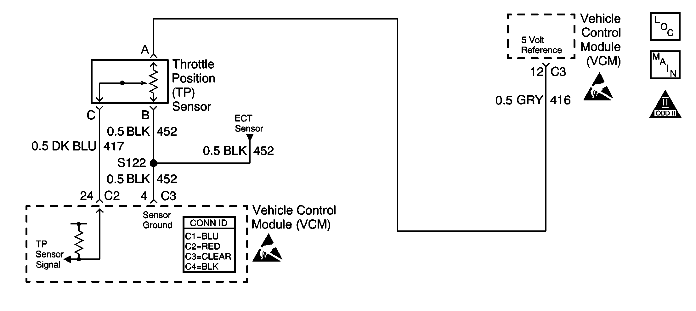
The throttle position (TP) sensor is a potentiometer. The control module supplies the TP sensor a reference voltage, a signal, and ground circuits. When the throttle is depressed, the TP sensor signal rises to near the reference voltage. When the throttle is released, the TP sensor signal decreases from the reference voltage. The control module monitors the TP sensor signal circuit voltage in order to determine the throttle blade angle, or opening.
This DTC is designed to detect an intermittent high signal voltage on the TP sensor signal circuit.
Conditions for Running the DTC
The engine is running.
Conditions for Setting the DTC
The vehicle control module (VCM) detects an intermittent high TP sensor voltage while the engine is running.
Action Taken When the DTC Sets
| • | The control module stores the DTC in history after the first failure but will not illuminate the malfunction indicator lamp (MIL). |
| • | The control module records the operating conditions at the time the diagnostic fails. The control module stores the failure information in the scan tools Freeze Frame/Failure Records. |
Conditions for Clearing the MIL/DTC
| • | A history DTC will clear if no fault conditions have been detected for 40 warm-up cycles. |
| • | A warm-up cycle occurs when the coolant temperature has risen 22°C (40°F) from the startup coolant temperature and the engine coolant temperature exceeds 70°C (160°F) during the same ignition cycle. |
| • | Use the scan tool Clear Information function. |
Diagnostic Aids
The scan tool reads the throttle position in volts. The scan tool should indicate about 0.45 to 0.85 volts with the throttle closed and the ignition switch turned ON or at idle. The voltage should increase at a steady rate as the throttle is moved toward the wide open throttle (WOT).
Some scan tools will read the throttle angle where 0 percent = closed throttle and 100 percent = WOT.
Observe the TP sensor while depressing the accelerator pedal with the ignition turned ON and the engine turned OFF. The display should vary from about 0.5 volts when the throttle was closed to more than 4.5 volts when the throttle is held at the WOT position.
This DTC could set if the TP sensor ground circuit is intermittently open or if the TP sensor signal circuit is intermittently shorted to voltage. If the high voltage reading is present, additional sensor circuit voltage codes could be set. Refer to any non-intermittent DTCs that are set.
Inspect for intermittents.
An intermittent may be caused by any of the following conditions:
| • | A poor connection |
| • | Rubbed through wire insulation |
| • | A broken wire inside the insulation |
Thoroughly inspect any circuitry that is suspected of causing the intermittent complaint. Refer to Testing for Intermittent Conditions and Poor Connections in Wiring Systems.
If a repair is necessary, refer to Wiring Repairs or Connector Repairs in Wiring Systems.
Test Description
The number below refers to the step number in the diagnostic table.
Step | Action | Values | Yes | No |
|---|---|---|---|---|
1 | Did you perform the Powertrain On-Board Diagnostic (OBD) System Check? | -- | ||
Is the voltage more than the specified value? | 4.7 V | Go to DTC P0123 Throttle Position (TP) Sensor Circuit High Voltage | ||
3 |
Did you find a problem? | -- | Go to Step 6 | |
4 |
Did you find a problem? | -- | ||
5 |
Does the voltage increase? | -- | Go to Diagnostic Aids | |
6 | Repair the circuit as necessary. Refer to Wiring Repairs or to Connector Repairs in Wiring Systems. Is the action complete? | -- | -- | |
7 |
Does the scan tool indicate the diagnostic Passed? | -- | ||
8 | Does the scan tool display any additional undiagnosed DTCs? | -- | Go to the applicable DTC table | System OK |
