The ignition system initiates combustion by providing a spark to ignite the compressed air and fuel mixture at the correct time. In order to provide an improved engine performance, fuel economy, and control of exhaust emissions, the control module controls the distributor spark advance, or timing, with the ignition control (IC) system.
The ignition system uses a primary and secondary sub system in order to accomplish the timed spark distribution. The primary system consists of a low voltage trigger device which determines the base timing. This signal is modified by the ignition control driver (ICD) module. The signal travels to either or both the engine and transmission processor (control module) for base timing reference. Another signal is sent back to the ignition control driver (ICD) module, which has been adjusted by the control module (advanced or retarded) in order to trigger the coil, according to the requirements of the engine.
The secondary system consists of the ignition coil which has primary, or low voltage, windings and secondary, or high voltage, windings. The secondary side of the ignition coil generates a high voltage which high tension spark plug wires deliver to the spark plugs.
The control module controller now controls the ignition control (IC) and bypass functions.
In order to properly control the ignition and combustion timing, the control module needs to know the following things:
| • | The crankshaft position |
| • | The engine speed or RPM |
| • | The engine load -- manifold pressure or vacuum |
| • | The atmospheric or barometric pressure |
| • | The engine coolant temperature |
| • | The camshaft position sensor |
System Operation
The enhanced ignition system used on all OBD II engines somewhat resembles the current distributor ignition (DI) system described in the ignition systems. However, the system has been greatly enhanced in order to make it compatible with the new OBD II regulations. The enhanced ignition system provides a spark at precisely the correct time in order to ignite the air and fuel mixture for optimum performance and fuel economy. The system consists of the following components:
| • | Vehicle control module (VCM) |
| • | Distributor |
| • | Ignition coil driver module |
| • | Ignition coil |
| • | Crankshaft position (CKP) sensor |
This system does not use the ignition module used on the DI systems in the past. The VCM controller now controls the ignition control (IC) and bypass functions.
The crankshaft sensor, located in the front engine cover, is perpendicular to a target wheel attached to the crankshaft. The target wheel is equipped with slots situated 60 degrees apart. As the crankshaft rotates, the target wheel rotates past the crankshaft position sensor. The rising and falling edges created by the slots cause a signal to be sent back to the VCM. This signal occurs three times per crankshaft revolution and is referred to as the 3x signal for V6 applications. The signal occurs four times per crankshaft revolution and is referred to as the 4x signal for V8 applications.
The VCM then utilizes this 3x (V6) or 4x (V8) signal in order to provide the correct spark to the engine by way of the single coil driver module. The single coil driver module is basically an electronic switch that when commanded by the VCM, causes the primary coil voltage to breakdown, energizing the secondary coil and providing a spark via the coil wire to the distributor cap. The distributor consists of the following components:
| • | Cap and rotor |
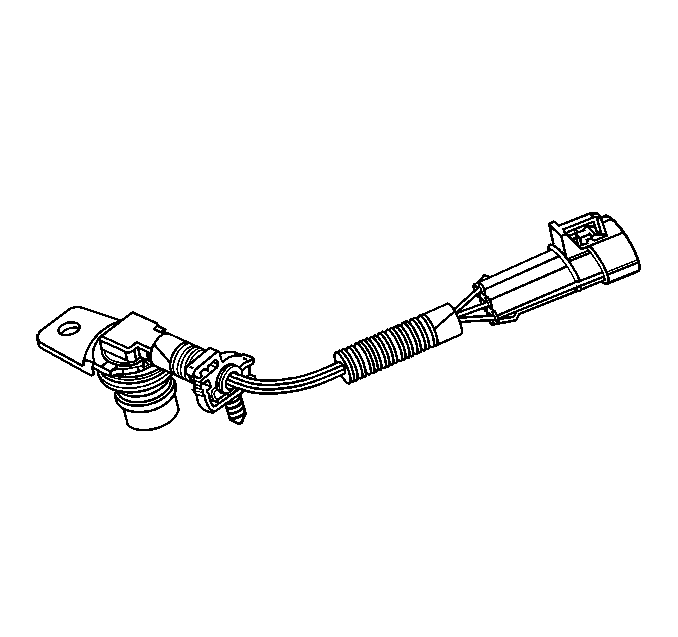
| • | Camshaft position (CMP) sensor |
| • | Gear drive and shaft |
The camshaft drives the distributor shaft which rotates providing a spark to the correct cylinder by way of the cap and rotor. The camshaft position sensor functions much like the crankshaft sensor previously described but provides only a 1x signal to the VCM. That is, for every 2 rotations of the crankshaft, there is 1 rotation of the camshaft. Note that the CMP sensor will not affect driveability. The sole purpose of the CMP sensor is to provide the VCM with the necessary information for the misfire DTCs.
Ignition Control (IC)
The vehicle control module (VCM) software controls all of the ignition control (IC) and bypass functions. This reduces the number of circuits outside of the controller and ultimately reduces the possibility for shorts or opens in those circuits that could result in driveability complaints or diagnostic trouble codes (DTCs).
System Components
Crankshaft Position Sensor

The crankshaft position (CKP) sensor is located in the front engine cover and is perpendicular to the crankshaft target wheel. The air gap between the sensor and the wheel is preset and not adjustable. The target wheel has four slots 60 degrees apart and is keyed to the crankshaft. As the target wheel rotates, the slots passing by the sensor create a change in the magnetic field of the sensor which results in an induced voltage pulse. One revolution of the crankshaft results in four pulses (4x signal). Based on these pulses, the VCM is able to determine crankshaft position and engine speed. The VCM then activates the fuel injector and provides a spark to the distributor. The relation between the CKP sensor and the target wheel is crucial. The sensor must be exactly perpendicular to the target wheel with the correct air gap.
Distributor

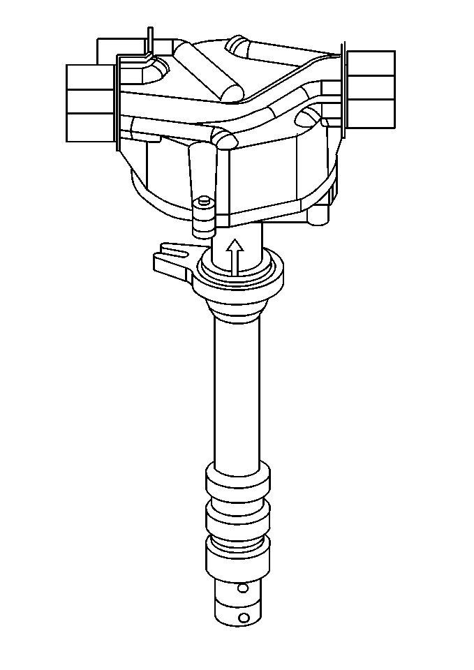
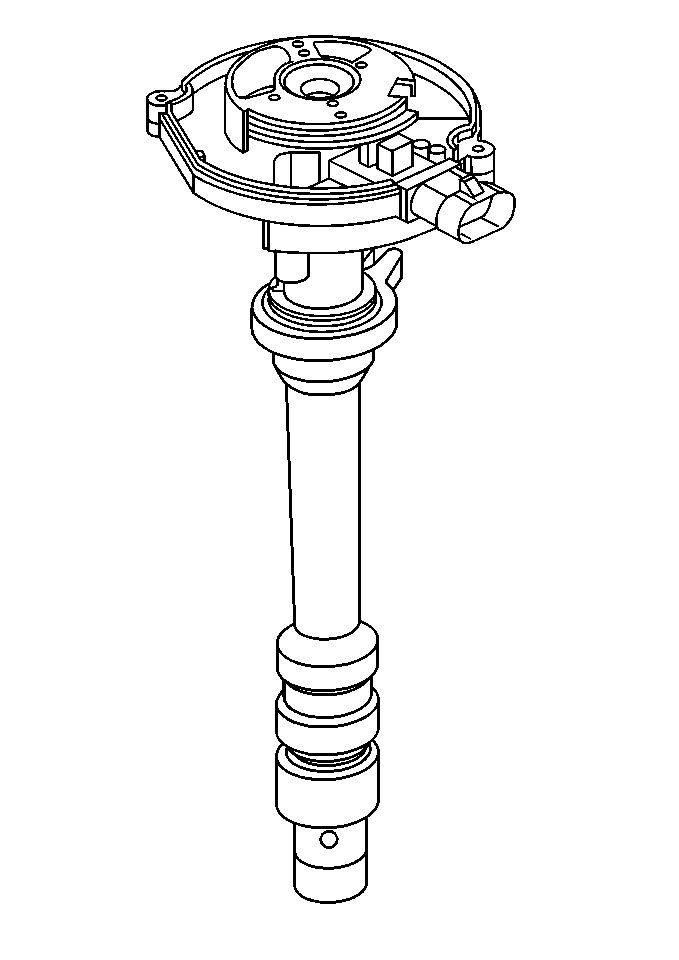
The distributor is actually an assembly that contains the camshaft position (CMP) sensor, cap, rotor, and shaft. The distributor is splined by a helical gear to the camshaft and rotates providing a spark to each spark plug wire. When servicing the distributor, it is critical to ensure proper cap sealing to the distributor body and correct installation to the camshaft. If the distributor is installed a tooth off in relation to the camshaft, a DTC sets. The distributor is repairable.
Camshaft Position Sensor

The camshaft position (CMP) sensor is located within the distributor. The operation is very similar to the crankshaft position (CKP) sensor however it provides one pulse per camshaft revolution (1x signal). This signal is not detrimental to the driveability of the vehicle. The VCM utilizes this signal in conjunction with the crankshaft position to determine which cylinders are misfiring.
Ignition Coil Driver Module and Ignition Coil
The ignition coil driver module is mounted on a bracket next to the coil. The VCM signals the ICD to turn ON primary current to the ignition coil by pulling the IC line high (4 volts). The ICD turns the primary current ON and OFF by applying and removing the ground to the primary winding at the appropriate time. This module is of minimum function. The module does not contain backup calibrations that allows the engine to continue to run if the IC signal is lost.
