Front Caster and Camber Adjustment RWD
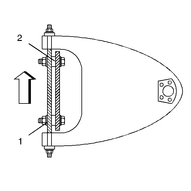
The caster and the camber adjustments are made by inserting shims between the upper control arm shaft and the frame bracket. The shims may be added, subtracted, or transferred in order to change the readings.
Important:
• Before adjusting the caster and the camber angles, jounce the
front bumper 3 times to allow the vehicle to return to the normal height. • Measure and adjust the caster and the camber with the vehicle
at curb height. The front suspension Z dimension and the rear suspension D
dimension are indicated in Trim Heights. Refer to
Trim Height Inspection
in Suspension General Diagnosis. • When checking the left and the right side caster and camber, it
must be equal within 1.0 degree. • When setting the left and the right side caster and camber, it
must be equal within 0.50 degree. • The caster and the camber set is relative to the ground.
- Loosen the upper control arm shaft to frame nuts (1).
- If the caster is not within specifications, adjust the caster by transferring the front shims to the rear, or the rear shims to the front.
- If the camber is not within specification, adjust the camber by changing the shims at both the front and the rear of the shaft. Add or subtract the shims (2) as required.
- Tighten the nut on the thinner shim pack first.
- Check the toe-in after changing the caster or the camber. Refer to Front Toe Adjustment .

Important:
• A normal shim pack will leave at least 2½ threads of the
bolt exposed beyond the nut. The maximum shim pack cannot be thicker than
21.3 mm (0.84 in). • The difference between the front shim packs and the rear shim
packs must not exceed 10 mm (0.40 in). If these requirements
cannot be met, check for damaged control arms and damaged related parts.
The transfer of the one shim from the rear bolt to the front bolt will decrease the positive caster.
Adding an equal number of shims at both the front and rear of the cross shaft will decrease positive camber.
Notice: Use the correct fastener in the correct location. Replacement fasteners must be the correct part number for that application. Fasteners requiring replacement or fasteners requiring the use of thread locking compound or sealant are identified in the service procedure. Do not use paints, lubricants, or corrosion inhibitors on fasteners or fastener joint surfaces unless specified. These coatings affect fastener torque and joint clamping force and may damage the fastener. Use the correct tightening sequence and specifications when installing fasteners in order to avoid damage to parts and systems.
Tighten
Tighten the nuts to 110 N·m (81 lb ft).
Tightening the nut on the thinner shim pack first improves the shaft to frame clamping force and torque retention.
Front Caster and Camber Adjustment AWD
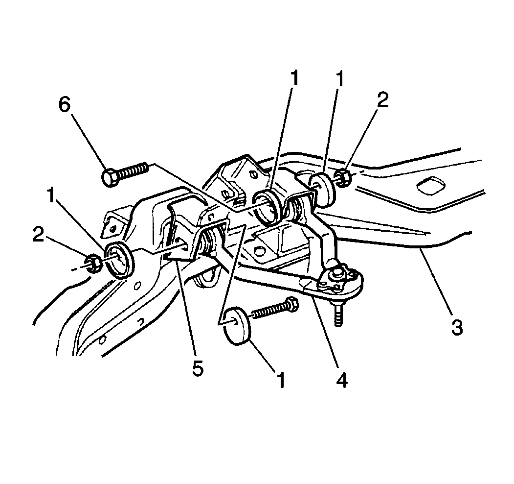
The caster and camber adjustments are made by rotating the offset cam bolt and the cam in the slotted frame bracket in order to reposition the control arm.
Important:
• Before adjusting the caster and the camber angles, jounce the
front bumper 3 times to allow the vehicle to return to the normal height. • Measure and adjust the caster and the camber with the vehicle
at curb height. The front suspension Z dimension and the rear suspension D
dimension are indicated in Trim Heights. Refer to
Trim Height Inspection
in Suspension General Diagnosis. • When checking the left and the right side caster, the right side
minus the left side must be equal within 0 degrees to 2.0 degrees. • When setting the left and the right side caster, the right side
minus the left side must be equal within 0.50 degrees to 1.50 degrees. • When checking the camber, it must be equal within 1.0 degrees. • When setting the camber, it must be equal within 0.50 degrees. • The caster and the camber set is relative to the ground.
- If the camber is not within specifications, adjust the camber using the following procedure:
- If the caster is not within specifications, adjust the caster using the following procedure:

Important: When this camber adjustment is followed, the caster setting will not be affected.
| 1.1. | Hold the cam bolt (6) and loosen the nut (2). |
| 1.2. | Rotate the cam (1) by rotating the bolt head (6). |
Turn the cam bolt in order to obtain change equal to ½ of the needed correction.
| 1.3. | Hold the cam bolt (6) in this position in order to maintain the setting. |
| 1.4. | Obtain the remaining ½ of the needed correction by repeating steps 1 through 3 to the other cam bolt. |
Turn the cam lobe in the same direction.
| 2.1. | Note the camber reading. |
| 2.2. | Hold the front cam bolt (6) and loosen the nut (2). |
| 2.3. | Turn the front cam bolt in order to obtain a change equal to ¼ of the desired caster change. |
At the front cam bolt, a positive camber change produces a positive caster change and a negative camber change produces a negative caster change.
| 2.4. | Hold the cam bolt (6) in this position while tightening the nut (2) in order to maintain setting. |
| 2.5. | Hold the rear cam bolt (6) and loosen the nut (2). |
| 2.6. | In order to return the camber to the setting that you noted earlier, turn the cam bolt (6) by turning the cam lobe (1) in the opposite direction. |
| 2.7. | Check the caster setting. |
Repeat the above procedure if not within specifications.
Notice: Use the correct fastener in the correct location. Replacement fasteners must be the correct part number for that application. Fasteners requiring replacement or fasteners requiring the use of thread locking compound or sealant are identified in the service procedure. Do not use paints, lubricants, or corrosion inhibitors on fasteners or fastener joint surfaces unless specified. These coatings affect fastener torque and joint clamping force and may damage the fastener. Use the correct tightening sequence and specifications when installing fasteners in order to avoid damage to parts and systems.
| 2.8. | When adjustments are complete, hold the cam bolt (6) head in order to ensure the cam position does not change while tightening the upper control arm mounting nut. |
Tighten
Tighten the upper control arm mounting nut to 140 N·m (103 lb ft).
