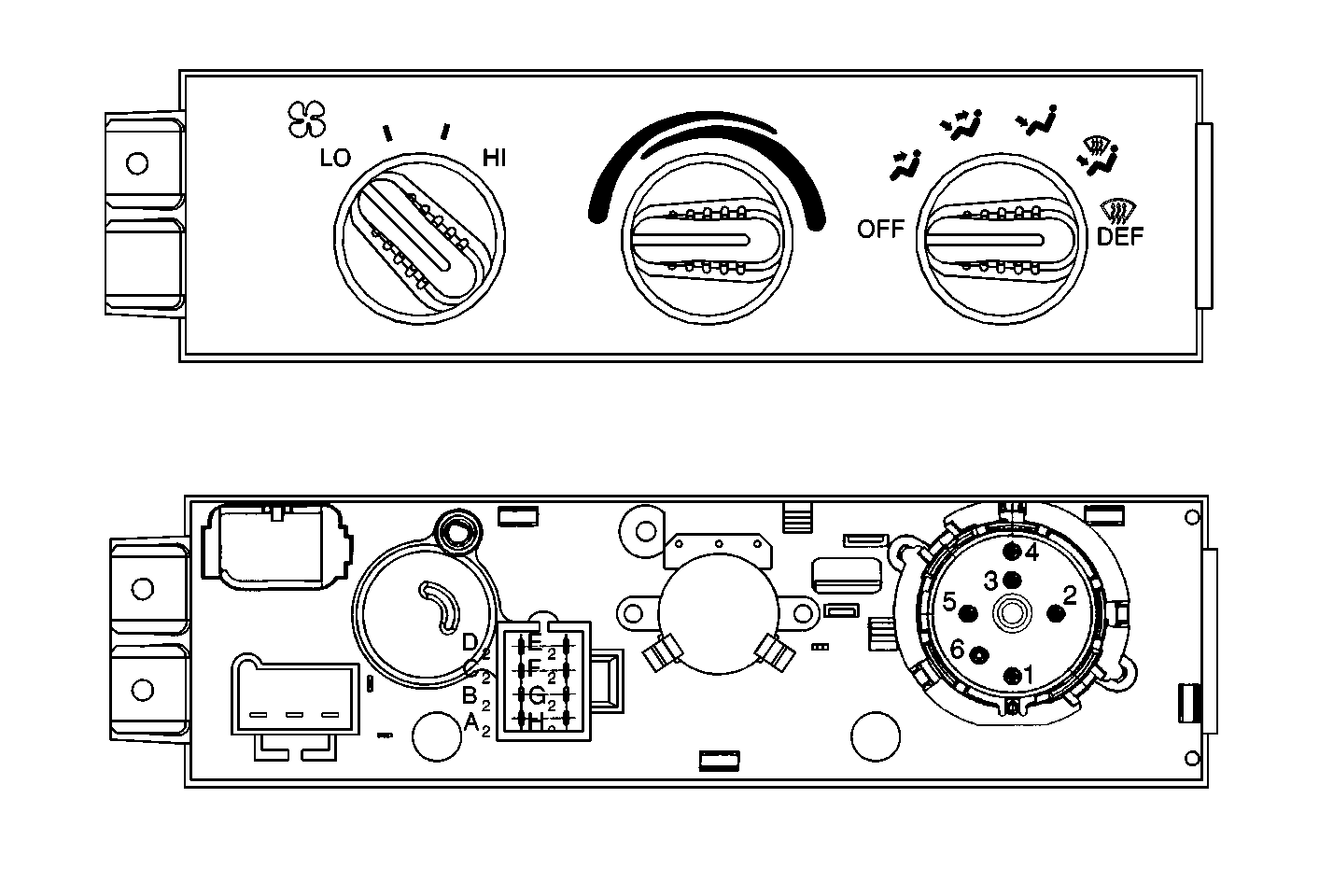
Perform the following
test using the control assembly in order to determine whether the following
systems are working properly:
| • | The refrigeration system |
- Check the blower motor speed from the LOW to the HIGH range in
order to verify the proper operation of the following components:
| • | The blower motor switch |
| • | The blower motor resistor |
| • | The high blower motor relay |
- Test each mode to verify the proper function of the following
systems:
| • | Proper air flow distribution |
| • | Correct function of the vacuum connections and their associated
parts |
| • | Correct function of the complete electrical system, including
the following: |
| • | The electrical actuators |
| • | The temperature sensors |
| • | The electrical connections and associated parts |
- Verify that each of the modes responds as follows:
| - | Air flows from the A/C outlets, including the lap air outlets. |
| - | The recirculation door closes. |
| - | The blower motor sounds louder than in the Normal A/C mode. |
| - | The A/C compressor operates. |
| - | Air flows from the A/C outlets, including the lap air outlets. |
| - | The recirculation door opens. |
| - | The A/C compressor operates. |
| - | Air flows from the A/C outlets, including the lap air and heater
outlets. |
| - | The A/C compressor operates. |
| - | Air flows from the A/C outlets, including the lap air outlets. |
| - | The A/C compressor does not operate. |
| - | A small amount of air flows from the heater outlet. |
| - | Air flows from the heater outlets. |
| - | A small amount of air flows from the defroster outlet and the
side window defoggers. |
| - | Air flows from the defroster outlet. |
| - | Air flows from the side window defoggers and the heater outlet. |
| - | The A/C compressor does not operate. |
| - | Air flows from the defroster outlet. |
| - | Air flows from the side window defoggers. |
| - | A small amount of air flows from the heater outlets. |
| - | The A/C compressor may operate. |
- Test the temperature control selector functions as follows:
| 4.1. | Check the temperature control knob effort by moving the knob from
the BLUE (cold) zone, to the RED (hot) zone. |
| 4.2. | Listen for the valve seating in the full BLUE (cold) zone and
the full RED (hot) zone. |
| 4.3. | Check for heated air by placing the temperature control knob in
the full RED (hot) zone and the mode knob in the Heater position. |
| 4.4. | Check for cooled air by placing the temperature control knob in
the full BLUE (cold) position and the mode knob in the MAX A/C or the NORM
A/C positions. |
Note the temperature of the air from the outlets. After one minute of
operation, the air from the A/C outlets should be at least -7°C
(20°F) below the ambient air temperature.
Checking the temperature range verifies the proper function of the following:
| • | All vacuum, electrical, and refrigerant system connections |
| • | All heater system connections |
| • | The air temperature door in the heater assembly |
| • | The temperature control knob for temperature selection |
