Tools Required
J 38778 Door Trim Pad and Garnish Clip Remover
Removal Procedure
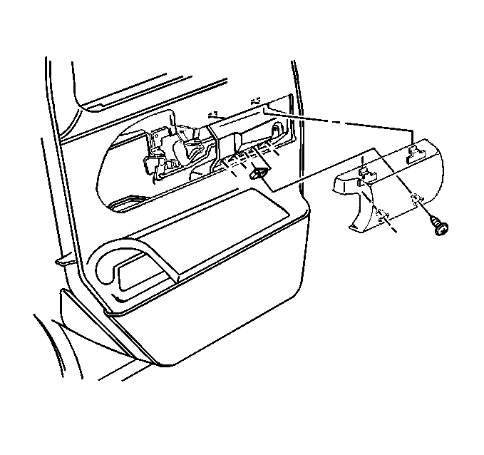
- Remove the screws and the armrest cover (YC5).
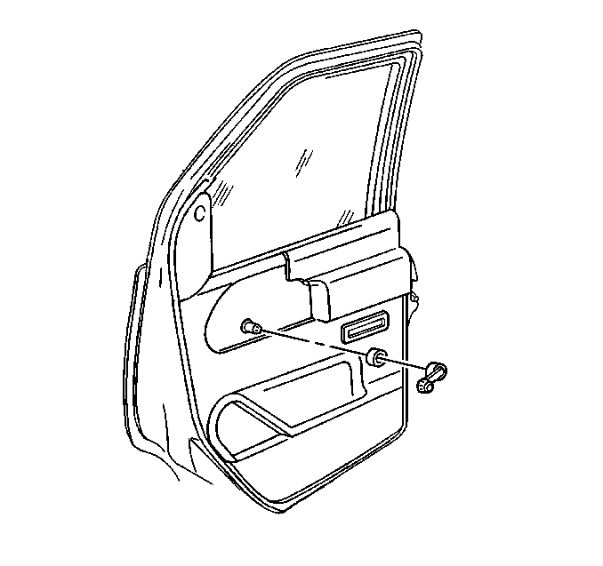
- Remove the window regulator handle, if equipped.
- Pull out on the lock lever escutcheon, starting with the front edge, in order to remove the lock lever escutcheon.
- Pull out on the top edge of the escutcheon and pivot down in order to clear the tab at the trim panel and remove the upper corner trim if equipped.
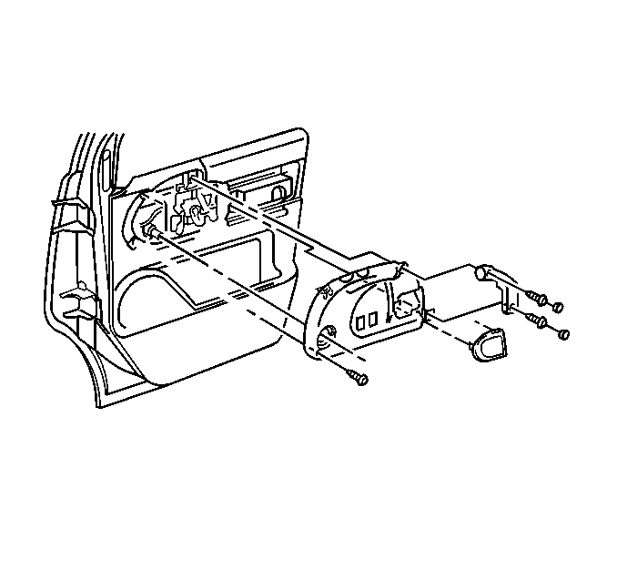
- Remove the caps that cover the screws retaining the assist handle.
- Remove the screws that retain the handle to the door.
- Remove the one screw at the front edge of the accessory switch mount plate.
- Remove the plate from the trim panel.
- Disconnect the electrical connectors from the switches on the plate, as needed.
- Remove the door courtesy lamp from the door panel, if equipped. Refer to Door Courtesy Lamp and Reflector Replacement .
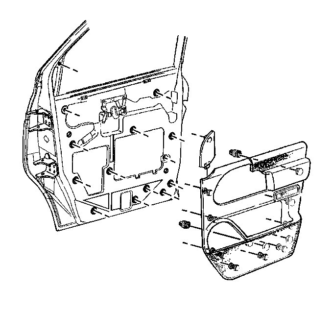
- Use J 38778 to release the door trim panel retainers.
- Remove the trim panel from the door.


Installation Procedure
Important: Replace any trim panel retainers that were damaged during removal.
- Position the trim panel to the door.
- Secure the trim panel retainers to the door by pressing into the door until fully seated.
- Place the window seal portion of the panel over the door frame in order to install the trim panel to the door.
- Install the door courtesy lamp to the door panel. Refer to Door Courtesy Lamp and Reflector Replacement .
- Connect the electrical connectors to the switches on the accessory switch mounting plate, as needed.
- Install the plate to the trim panel.
- Install the one screw at the front edge of the accessory switch mount plate.
- Install the handle to the door with screws.
- Install the caps that cover the screws on the assist handle.
- Insert the tab in the slot on the door trim panel and seat the fastener into the door at the top in order to install the upper corner trim.
- Push the lock lever escutcheon into place, starting at the rear edge.
- Install the window regulator handle, if equipped.
- Install the armrest cover and the screws (YC5).
Notice: Use the correct fastener in the correct location. Replacement fasteners must be the correct part number for that application. Fasteners requiring replacement or fasteners requiring the use of thread locking compound or sealant are identified in the service procedure. Do not use paints, lubricants, or corrosion inhibitors on fasteners or fastener joint surfaces unless specified. These coatings affect fastener torque and joint clamping force and may damage the fastener. Use the correct tightening sequence and specifications when installing fasteners in order to avoid damage to parts and systems.
Tighten
Tighten the one screw at the front edge of the accessory switch mount
plate to 2 N·m (18 lb in).
Tighten
Tighten the handle to the door with screws to 5 N·m (44 lb in).


Tighten
Tighten the armrest cover screws to 5 N·m (44 lb in).
