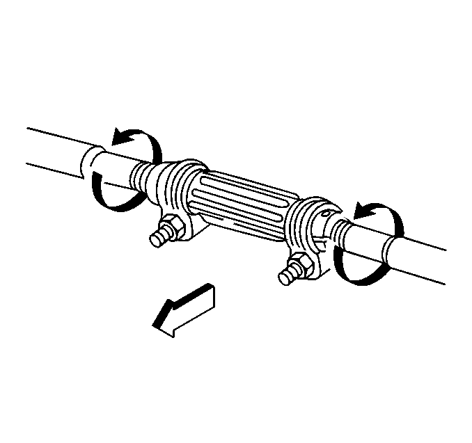
The toe-in can be increased or decreased by changing the length of the tie rods. A threaded sleeve is provided for this purpose. When the tie rods are mounted ahead of the steering knuckle, the tie rods must be modified as follows:
| • | Decreased in length in order to increase the toe-in. |
| • | Increased in length in order to decrease the toe-in. |
Important:
• When checking and setting the toe-in, the left and right side
to be set separately and the steering wheel must be held straight ahead
position within 4 - 6 degrees. • Before adjusting the toe-in, jounce the front bumper 3 times
to allow the vehicle to return to the normal height. • Adjust the toe-in with the vehicle at curb height. The front suspension
Z dimension and the rear suspension D dimension are indicated in Trim Heights.
Refer to
Trim Height Inspection
in Suspension General Diagnosis. • For an accurate toe-in reading, do not push or pull on the tires
during the alignment process.
- Set the steering wheel in the straight ahead position.
- Loosen the clamp bolts at each end of the steering tie rod adjustable sleeves.
- If the torque needed to rotate the adjuster tube exceeds 9 N·m (80 lb in), perform the following steps:
- Rotate the inner and the outer tie rod sockets rearward to the limit of the ball stud travel.
- Turn the tie rod adjusting sleeves to set the toe-in to specifications. Refer to Wheel Alignment Specifications .
- Tighten the adjuster tube clamp nuts.
- Rotate the tie rod sockets to the centered position.
Important: The tie rod adjuster often becomes rusted in service.
| 2.1. | Remove the adjuster tube clamp nuts and the bolts. |
Discard the nuts and the bolts.
| 2.2. | Apply the penetrating oil between the adjuster tube and the tie rod threads. |
| 2.3. | Rotate the adjuster tube until the tube moves freely. |
| 2.4. | Install the new bolts and the nuts with the correct part number. The nut must be towards the front of the vehicle. |


Notice: Use the correct fastener in the correct location. Replacement fasteners must be the correct part number for that application. Fasteners requiring replacement or fasteners requiring the use of thread locking compound or sealant are identified in the service procedure. Do not use paints, lubricants, or corrosion inhibitors on fasteners or fastener joint surfaces unless specified. These coatings affect fastener torque and joint clamping force and may damage the fastener. Use the correct tightening sequence and specifications when installing fasteners in order to avoid damage to parts and systems.
Important: Before tightening the adjuster tube nuts, do the following:
• Check the number of threads on each tie rod within the adjuster
tube. The tie rod threads within the adjuster tube must be equal to within
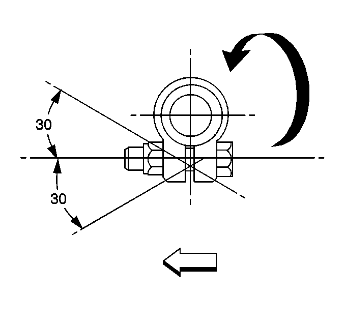
3 threads. • Check the relationship of the adjuster tube to the clamp. The adjuster tube slot and the clamp opening must not be in the same
position. The position of the adjuster tube clamp must not exceed 30 degrees in
either direction. • The adjuster tube clamp must be on the inside of the adjuster
tube dimple.
Tighten
Tighten the adjuster tube clamp nuts to 25 N·m (18 lb ft).
The clamp ends may touch when the nuts are tightened to specification.
Ensure that the outer socket is square with the stud.
