For 1990-2009 cars only
Tools Required
J 21366 Converter Holding Strap
Removal Procedure
- Disconnect the battery. Refer to Battery Negative Cable Disconnection and Connection in Engine Electrical.
- Raise the vehicle. Refer to Lifting and Jacking the Vehicle in General Information.
- Remove the rear propeller shaft. Refer to Rear Propeller Shaft Replacement in Propeller Shaft.
- Support the transmission with a transmission jack.
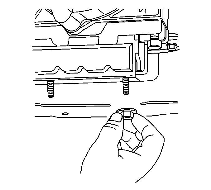
- Remove the nut (2WD) or nuts (AWD) securing the transmission mount to the transmission support.
- Raise the transmission slightly and remove the transmission support from the vehicle. Refer to Transmission Support Replacement in Frame and Underbody.
- Remove the front exhaust pipe assembly. Refer to Catalytic Converter Replacement in Engine Exhaust.
- Remove the starter motor. Refer to Starter Motor Replacement in Engine Electrical.
- Lower the transmission to gain access to the top and sides of the transmission.
- Disconnect the vent tube hose and the electrical connections from the transfer case, if equipped.
- Remove the transmission mount. Refer to Transmission Rear Mount Replacement .
- Remove the transfer case, if equipped. Refer to Transfer Case Assembly Replacement in Transfer Case - NVG 136-NP4 (One Speed Automatic).
- Remove the range selector cable end from the transmission range selector lever ball stud and bracket. Refer to Range Selector Lever Cable Replacement .
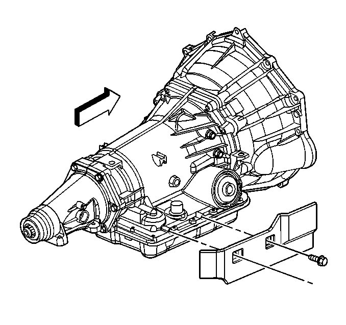
- Remove the transmission heat shield. Refer to Transmission Heat Shield Replacement .
- Disconnect the transmission vent hose, the park/neutral position switch connector, and the main electrical connector from the transmission. Refer to Park/Neutral Position Switch Replacement .
- Remove the bolt that secures the fuel line bracket to the left side of the transmission.
- Remove the torque converter access plug.
- Remove the flywheel to torque converter bolts.
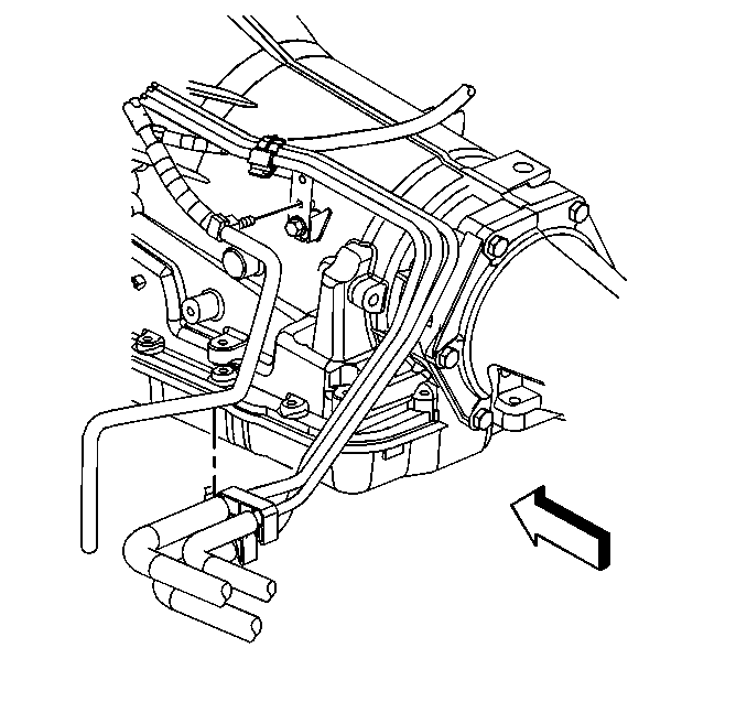
- Disconnect the transmission oil cooler pipes from the transmission. Refer to Transmission Fluid Cooler Hose/Pipe Replacement .
- Plug the transmission oil cooler pipe connectors in the transmission case.
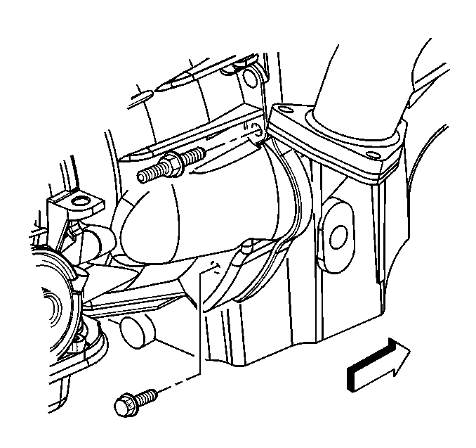
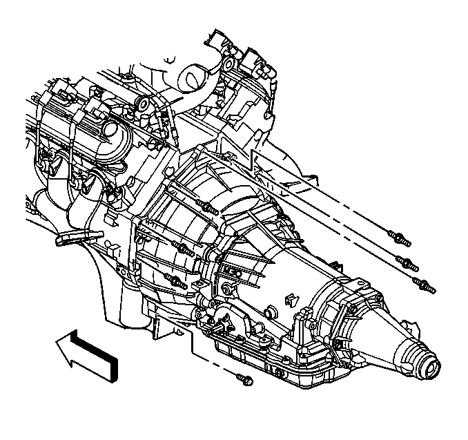
- Remove the stud and the bolt securing the transmission to the engine.
- Remove the six studs and one bolt securing the transmission to the engine.
- Install the J 21366 onto the transmission bell housing to retain the torque converter.
- Pull the transmission straight back.
- Remove the transmission from the vehicle while simultaneously removing the fluid level indicator tube.
- Flush the transmission oil cooler and lines. Refer to Transmission Fluid Cooler Flushing and Flow Test .
Installation Procedure
- Install the J 21366 onto the transmission bell housing to retain the torque converter.
- Support the transmission with a transmission jack.
- Raise the transmission into place while simultaneously installing the fluid indicator tube.
- Remove the J 21366 from the transmission.
- Slide the transmission straight onto the locating pins while lining up the marks on the flywheel and the torque converter.
- Install six studs and one bolt securing the transmission to the engine.
- Install the stud and bolt securing the transmission to the engine.
- Install the flywheel to torque converter bolts.
- Install the torque converter access plug.
- Install the transmission vent hose, fuel lines, and the wiring harness to the transmission.
- Install the heat shield to the transmission. Refer to Transmission Heat Shield Replacement .
- Install the range selector cable to the range selector lever ball stud and the bracket. Refer to Range Selector Lever Cable Replacement .
- Install the transfer case, if equipped. Refer to Transfer Case Assembly Replacement in Transfer Case - NVG 136-NP4 (One Speed Automatic).
- Install the transmission mount to the transmission (2WD) or the transfer case adapter (AWD). Refer to Transmission Rear Mount Replacement .
- Connect the vent hose and electrical connectors to the transfer case, if equipped.
- Install the starter motor. Refer to Starter Motor Replacement in Engine Electrical.
- Install the front exhaust pipe assembly. Refer to Catalytic Converter Replacement in Engine Exhaust.
- Install the transmission support to the vehicle. Refer to Transmission Support Replacement in Frame and Underbody.
- Install the transmission mount to transmission support nut (2WD) or nuts (AWD).
- Remove the transmission jack.
- Install the rear propeller shaft. Refer to Rear Propeller Shaft Replacement in Propeller Shaft.
- Flush the transmission oil cooler and oil cooler pipes at this time, if necessary. Refer to Transmission Fluid Cooler Flushing and Flow Test .
- Connect the oil cooler pipes to the transmission. Refer to Transmission Fluid Cooler Hose/Pipe Replacement .
- Lower the vehicle.
- Connect the battery. Refer to Battery Negative Cable Disconnection and Connection in Engine Electrical.
- Fill the transmission to the proper level with DEXRON® VI transmission fluid, if necessary. Refer to Transmission Fluid Check .
- Reset the TAP values. Refer to Transmission Adaptive Functions .
- Test the vehicle for proper operation and check for leaks.
The torque converter must rotate freely by hand.
Notice: Refer to Fastener Notice in the Preface section.

Tighten
Tighten the studs and the bolt to 42 N·m (35 lb ft).

Tighten
Tighten the stud and the bolt to 47 N·m (35 lb ft).
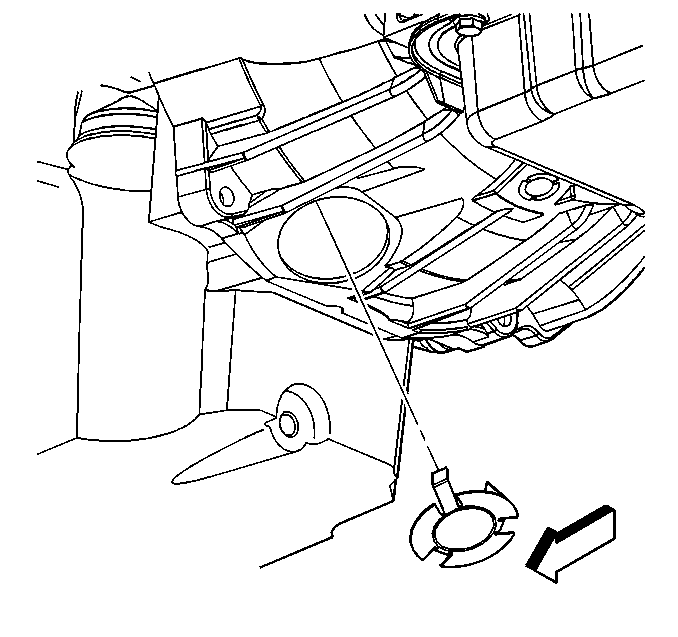
Tighten
Tighten the bolts to 63 N·m (46 lb ft).


Tighten
Tighten the nut (2WD) or nuts (AWD) to 40 N·m (29 lb ft).
Important: It is recommended that transmission adaptive pressure (TAP) information be reset.
Resetting the TAP values using a scan tool will erase all learned values in all cells. As a result, The ECM, PCM or TCM will need to relearn TAP values. Transmission performance may be affected as new TAP values are learned.