General Description
The ignition system includes the following components:
| • | The primary and secondary wiring |
Service Precautions
| • | Some service tachometers and electronic diagnostic equipment may
NOT be compatible with this ignition system. Consult your representative
of such equipment. |
| • | When making compression tests, disconnect the engine harness connection
to the ignition coil. |
| • | The distributor does not require periodic lubrication. Engine
oil lubricates the lower bushing. The upper bushing is prelubricated and
sealed. |
| • | The material used to construct the spark plug wires is very pliable
and soft. This wire will withstand high heat and carry a high voltage. Due
to the more pliable wire, scuffing and cutting become easier. Route the
spark plug wires correctly in order to prevent chafing or cutting. When
removing a spark plug wire from a spark plug, twist the boot on the spark
plug and pull on the boot in order to remove the wire. |
Distributor Ignition (DI) System
The distributor ignition (DI) system includes the following components:
| • | A crankshaft position (CKP) sensor |
The vehicle control module (VCM) controls the ignition system. The VCM
performs the following functions:
| • | Monitors information from various engine sensors |
| • | Computes the desired spark timing |
| • | Controls the dwell and firing of the ignition coil (through an
ignition control line to the coil driver) |
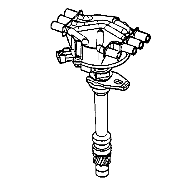
The distributor connects the ignition coil and spark plugs through secondary
wires. The rotor directs the spark to the appropriate cylinder. The distributor
has a hall-effect switch that connects to the VCM through the primary engine
harness. This switch provides cylinder identification information.
Identification
The part number is pin stamped into the plastic base, directly below
the high tension terminals and next to the three pin camshaft sensor connection.
Ignition Coil
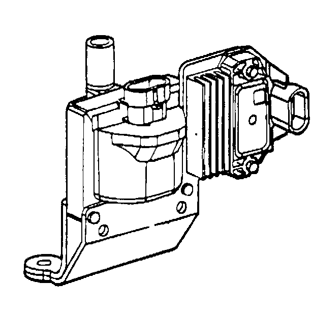
When signaled by the VCM, the coil driver controls the current flow
in the primary winding of the ignition coil. The primary engine harness makes
the interconnects. The ignition coil can generate up to 35,000 volts
and connects to the distributor through a secondary wire.
Secondary Wires
The secondary wires carry voltage between the ignition coil, the distributor,
and the spark plugs. The secondary wire connections form a tight seal that
prevents voltage arcing.
Hall-Effect Switch
The hall-effect switch connects to the VCM through the primary engine
harness. The hall-effect switch provides cylinder identification information.
The hall-effect switch is under the distributor cap.
Crankshaft Position Sensor
The crankshaft position (CKP) sensor connects to the VCM through the
primary engine harness. The crankshaft position sensor provides crankshaft
reference information to the VCM for spark and fuel delivery. The crankshaft
position sensor is in the front cover behind the crankshaft balancer.
Ignition Base Timing
Notice: The distributor used with the OBD II ignition system is located in a
fixed, non-adjustable position. Do not adjust the engine base timing by rotating
this distributor. Otherwise, crossfiring and damage to the distributor will
result.
Spark Plugs
These engines use resistor-type, tapered-seat spark plugs. These plugs
do not have a gasket. These spark plugs are High Efficiency (HE) spark plugs
that have a fine wire electrode, a nickel plated shell, and a platinum
pad across from the electrode. These features give the HE spark plug long
life and durability. For correct spark plug gap information, refer to
Maintenance Items
in Maintenance
and Lubrication.
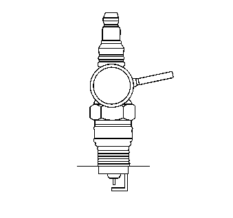
If the spark plug shell hex is not fully engaged in the spark plug socket
wrench, the socket may cock at an angle and cause insulator cracking or breakage
during plug installation or removal.
Normal or average service is assumed to be a mixture of idling, low
speed, and high speed operation with some of each making up the daily total
driving. Occasional or intermittent high speed driving is essential for
good spark plug performance. High speed driving provides increased and
sustained combustion heat that burns away any excess deposits of carbon,
or oxide, that may accumulate from frequent idling, continual stop-and-go,
or slow speed driving. An insulating boot made of special heat-resistant
material that covers the spark plug terminal, and extends downward over
a portion of the plug insulator, protects the spark plugs. These boots
prevent flash-over with resultant misfire of the engine, even though a
film is allowed to accumulate on the exposed portion of the plug porcelains.
Do not mistake corona discharge for flash-over or a shorted insulator.
Corona discharge is a steady blue light appearing around the insulator, just
above the shell crimp. This is the visible evidence of a high-tension field,
and has no effect on the ignition performance. You usually can only detect
corona discharge in darkness. This discharge may repel dust particles,
leaving a clear ring on the insulator just above the shell. This ring is
sometimes mistakenly regarded as evidence that combustion gases have blown
out between the shell and the insulator.
Spark Plug Wires
A rubber jacket encases the spark plug wiring. The silicone spark plug
boots form a tight seal on the plugs. Refer to the following illustrations
for the proper routing of the spark plug wires:
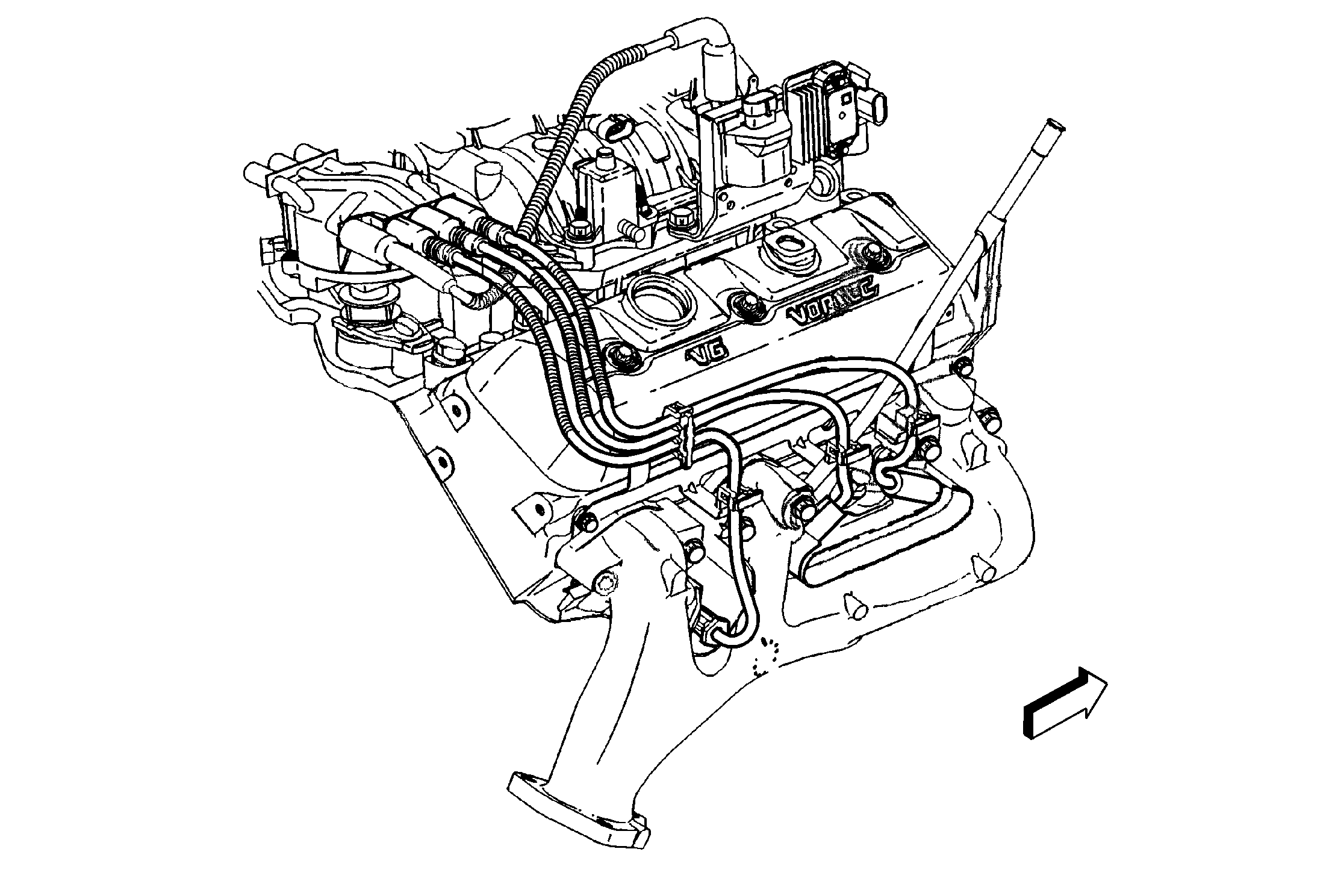
For the right side, route the wires as shown.
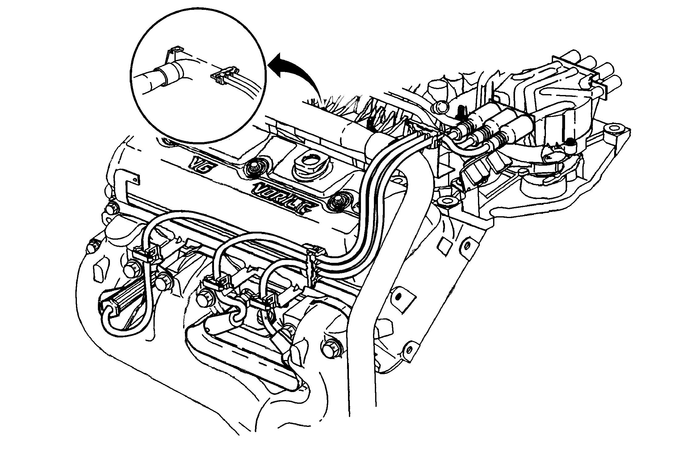
For the left side, route the wires as shown.


