For 1990-2009 cars only
Tools Required
| • | J 8001 Dial Indicator |
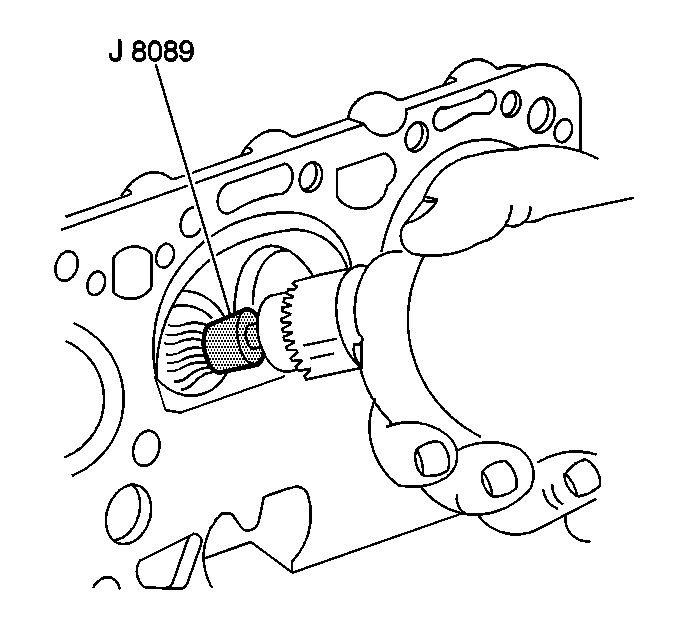
| • | J 8089 Carbon Removal Brush |
| • | J 9666 Valve Spring Tester |
- Use the J 8089 in order to clean the carbon from the combustion chambers. Be careful not to scuff the chambers.
- Clean the valve stems and heads of a buffing wheel.
- Clean the following components in solvent:
- Dry the components with compressed air.
- Measure the cylinder head for warpage with a straight edge and feeler gauge.
- Use the J 9666 in order to measure the valve spring.
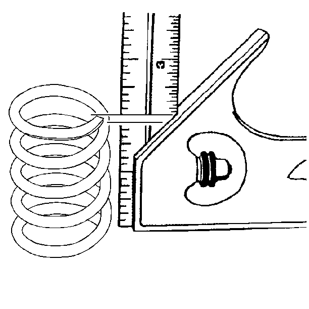
- Inspect the valve springs for squareness.
- Valve stems (1) with excessive guide (2) clearance must be repaired or replaced.
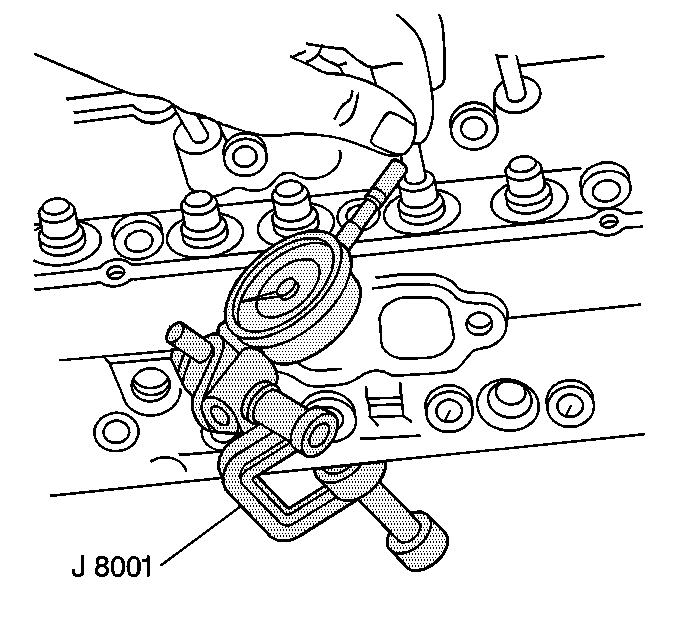
- Measure the valve stem-to-guide clearance.
Caution: Wear safety glasses in order to avoid eye damage.
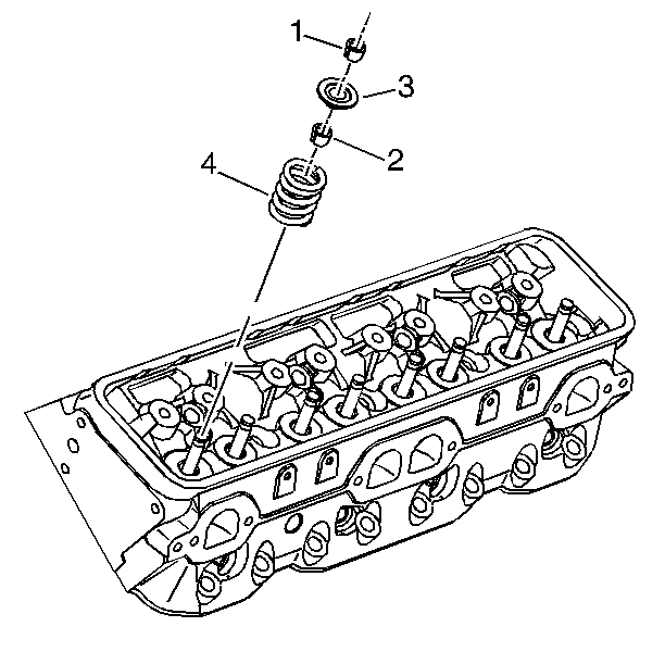
| • | Valve stem keys (1) |
| • | Valve spring cap (3) |
| • | Valve spring (4) |
| • | Cylinder head |
Caution: Wear safety glasses in order to avoid eye damage.
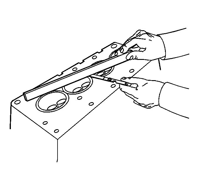
| 5.1. | A cylinder head block deck with warpage in excess of 0.10 mm (0.004 in) within a 152.4 mm (6.0 in) area must be repaired or replaced. |
| 5.2. | A cylinder head exhaust manifold deck with warpage in excess of 0.5 mm (0.002 in) within a 152.4 mm (6.0 in) area must be repaired or replaced. |
| 5.3. | A cylinder head intake manifold deck with warpage in excess of 0.10 mm (0.004 in) within a 152.4 mm (6.0 in) area must be repaired or replaced. |
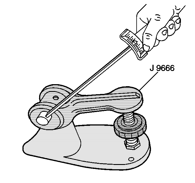
Replace the valve spring if the spring tension is less than 338 N (76 lb) at 43.2 mm (1.70 in).
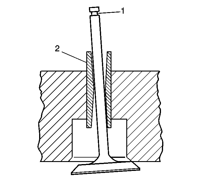
| • | Excessive valve stem-to-guide clearance may cause excessive oil consumption and may also cause a valve to break. Insufficient clearance will result in noisy and sticky functioning of the valve and will disturb the engine assembly smoothness. |
| • | Clamp the J 8001 on the exhaust port side of the cylinder head. |
| • | Locate the indicator so that the movement of the valve stem from side to side (crosswise to the cylinder head) will cause a direct movement of the indicator stem. |
| • | The indicator stem must contact the side of the valve stem just above the valve guide. |
| • | Drop the valve head about 1.6 mm (0.0064 in) off the valve seat. |
| • | Use light pressure when moving the valve stem from side to side in order to obtain a clearance reading. |
