Removal Procedure
- Remove the air cleaner. Air Cleaner Assembly Replacement in Engine Controls.
- Discharge and recover the refrigerant from the system. Refer to Refrigerant Recovery and Recharging .
- Raise the vehicle.
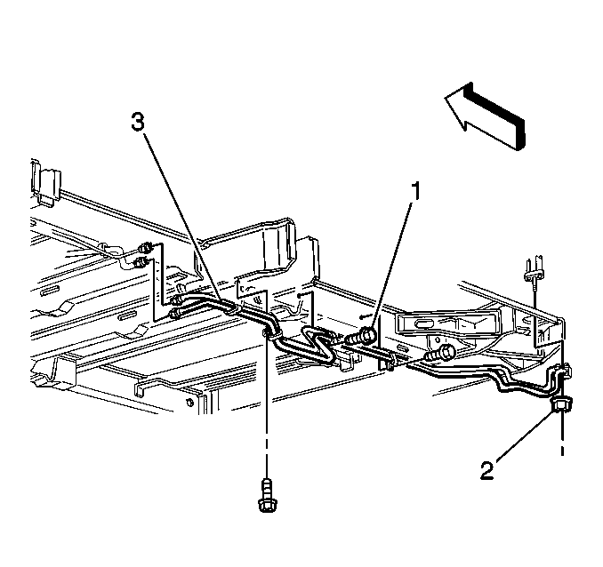
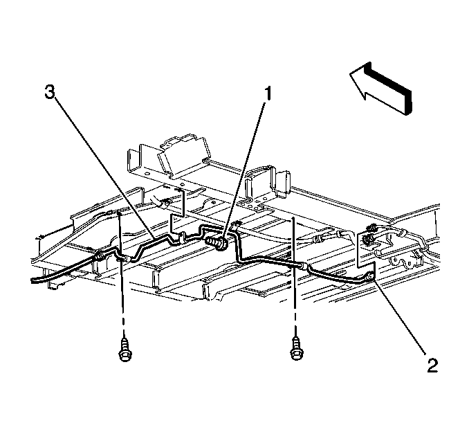
- Remove the auxiliary evaporator side inlet tube from the auxiliary evaporator rear tube (3) assembly.
- Remove the O-ring seal.
- Remove the auxiliary evaporator side inlet tube from the auxiliary evaporator front tube (2).
- Remove the O-ring seal.
- Remove the bolts (1) that retain the clips on the auxiliary side inlet tube (3) to the body.
- Remove the auxiliary evaporator side inlet tube (3) from the vehicle.
Installation Procedure
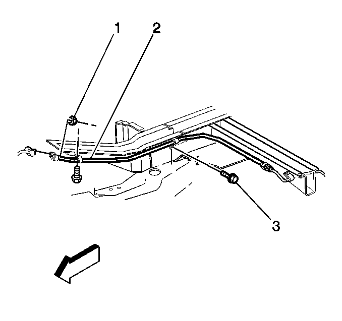
- Install the auxiliary evaporator side inlet tube (3) to the vehicle.
- Install the bolts that retain the clips on the auxiliary evaporator side inlet tube (3) to the body.
- Install the new O-ring seal.
- Install the auxiliary evaporator side inlet tube to the auxiliary evaporator front inlet tube (2).
- Install the new O-ring seal.
- Install the auxiliary evaporator side inlet tube (3) to the auxiliary evaporator rear tube assembly.
- Lower the vehicle.
- Evacuate and charge the system. Refer to Refrigerant Recovery and Recharging
- Ensure that no leaks exist in the system.
- Install the air cleaner. Refer to Air Cleaner Assembly Replacement in Engine Controls.
Notice: Use the correct fastener in the correct location. Replacement fasteners must be the correct part number for that application. Fasteners requiring replacement or fasteners requiring the use of thread locking compound or sealant are identified in the service procedure. Do not use paints, lubricants, or corrosion inhibitors on fasteners or fastener joint surfaces unless specified. These coatings affect fastener torque and joint clamping force and may damage the fastener. Use the correct tightening sequence and specifications when installing fasteners in order to avoid damage to parts and systems.
Tighten
Tighten the bolts that retain the clips on the auxiliary evaporator
side inlet tube (3) to the body to 5 N·m (44 lb in).
Coat the O-ring seal with 525 viscosity refrigerant oil.
Tighten
Tighten the fitting to 27.5 N·m (20 lb ft).
Coat the O-ring seal with 525 viscosity refrigerant oil.
Tighten
Tighten the fitting to 27.5 N·m (20 lb ft).
