Removal Procedure
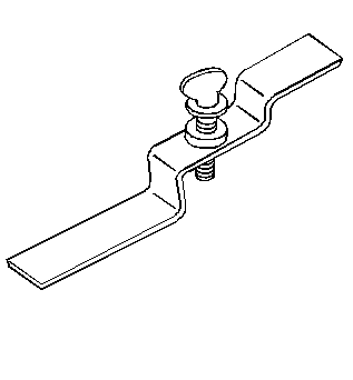
Tools Required
J 21366 Converter Holding Strap
- Raise the vehicle. Refer to Lifting and Jacking the Vehicle in General Information.
- Drain the transmission fluid. Refer to Automatic Transmission Fluid and Filter Replacement .
- Remove the range select cable from the transmission.
- RWD Vehicles: Remove the rear propeller shaft. Refer to Propeller Shaft Replacement (Rear) or Propeller Shaft Replacement (Front) in Propeller Shaft.
- AWD Vehicles:
- AWD Vehicles: Remove the two front torsion bars. Refer to Torsion Bar Replacement in Front Suspension.
- Remove the crossmember and the crossover pipe.
- Lower the transmission enough in order to provide assess to other components.
- Remove the fluid fill tube and the fill tube seal from the transmission. Refer to Filler Tube Replacement .
- Plug the fluid fill tube opening in the transmission.
- Disconnect the wiring harness connector from the vehicle speed sensor and from the park/neutral position switch.
- Remove the remaining electrical connectors from the transmission.
- Disconnect the transmission oil cooler pipes from the transmission. Refer to Oil Cooler Hose/Pipe Replacement for the proper procedure.
- Plug the transmission oil cooler pipe connectors in the transmission case.
- Remove the starter motor.
- Remove the two screws securing the transmission cover to the engine.
- Mark the flywheel and the torque converter alignment.
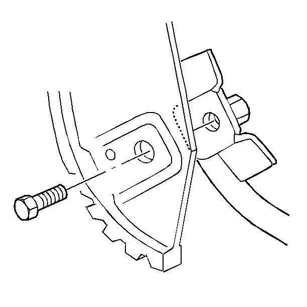
- Remove the bolts that attach the torque converter to the engine flywheel.
- Support the engine with a suitable jack stand before removing the transmission from the engine.
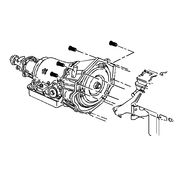
- Remove nine bolts securing the transmission to the engine. Note the location of any brackets or clips.
- Pull the transmission straight back from the engine.
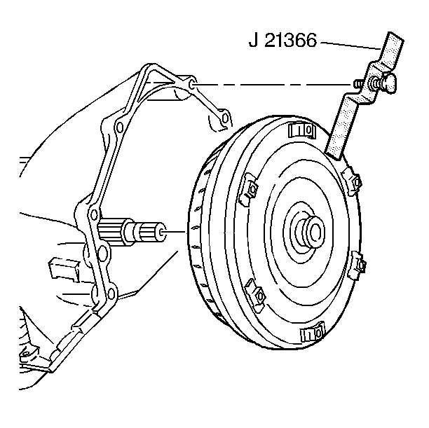
- Install the J 21366 in order to keep the torque converter from sliding off of the transmission turbine shaft.
- Remove the transmission from the vehicle.
- Flush the transmission oil cooler and the pipes whenever you remove the transmission for overhaul, or replacement of the torque converter, the pump, or the transmission case. Refer to Transmission Fluid Cooler Flushing .
- Clean the transmission case using a solvent dampened cloth. Do not allow solvent to enter the transmission.
- Air dry the transmission.
- Clean all hardware and the flywheel cover using solvent. Air dry all the parts.
- Inspect all the components for wear and damage.
- Inspect all the seals and the fittings for signs of wear.
- Inspect the torque converter for stripped or broken weld nuts.
- Inspect the transmission case for cracks.
| 5.1. | Support the transmission with a transmission jack. |
| 5.2. | Remove the front propeller shaft from the transfer case. |
| 5.3. | Remove the transfer case and the adapter from the transmission. Refer to Transfer Case Replacement (Manual Four Wheel Drive) in Transfer Case. |
Installation Procedure
Tools Required
J 21366 Converter Holding Strap
- Install the J 21366 in order to keep the torque converter from sliding off of the transmission turbine shaft.
- Raise the transmission into place and remove the J 21366 .
- Support the transmission with a transmission jack.
- Slide the transmission straight onto the locating pins while lining up the marks on the flywheel and the torque converter.
- Install the nine bolts securing the transmission to the engine. Be sure to install the brackets, the clips, and the harnesses to the original locations. Do not install the oil level indicator tube.
- Install the three bolts securing the torque converter to the engine flywheel.
- Tighten the bolts finger tight to insure proper converter seating.
- Tighten the bolts to 63 N·m (46 lb ft).
- Install the transmission cover.
- Install the starter motor.
- Remove the two plugs from the transmission case cooler pipe connectors.
- Install the transmission oil cooler pipes. Refer to Oil Cooler Hose/Pipe Replacement .
- Connect the wiring harness connectors to the vehicle speed sensor and to the park/neutral position switch.
- Install all vehicle electrical harness wires, harness clips, tubes, and brackets removed before transmission removal.
- Install the transmission fluid fill tube and the fill tube seal. Refer to Filler Tube Replacement .
- AWD Vehicles: Install the transfer case and the adapter to the transmission.
- RWD Vehicles: Install the rear propeller shaft. Refer to Propeller Shaft Replacement (Rear) in Propeller Shaft.
- AWD Vehicles: Install the propeller shafts to the transfer case. Refer to Propeller Shaft Replacement (Rear) in Propeller Shaft.
- AWD Vehicles: Install the front torsion bars.
- Install the transmission range select cable to the transmission range select lever and the bracket.
- Remove the safety stands.
- Lower the vehicle.
- Fill the transmission with new transmission fluid. Refer to Fluid Capacity and to Transmission Fluid Check .
Important: The torque converter must be flush onto the flywheel and rotate freely by hand.
Notice: Use the correct fastener in the correct location. Replacement fasteners must be the correct part number for that application. Fasteners requiring replacement or fasteners requiring the use of thread locking compound or sealant are identified in the service procedure. Do not use paints, lubricants, or corrosion inhibitors on fasteners or fastener joint surfaces unless specified. These coatings affect fastener torque and joint clamping force and may damage the fastener. Use the correct tightening sequence and specifications when installing fasteners in order to avoid damage to parts and systems.
Tighten
Tighten the bolts to 32 N·m (23 lb ft).
Tighten
Tighten
Tighten the bolts to 10 N·m (89 lb in).
