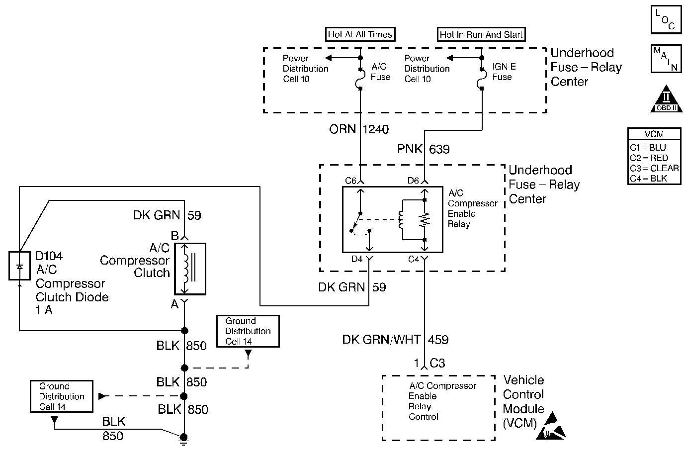
Circuit Description
The VCM control of the A/C clutch improves idle quality and performance by performing the following conditions:
| • | Delaying clutch engagement until the idle speed is increased |
| • | Releasing the clutch when the idle speed is too low |
| • | Providing additional fuel at the instant the clutch is applied |
The additional fuel smooths the cycling of the compressor.
Turning the air conditioning ON supplies battery voltage through the pressure switches to the VCM. When the VCM receives the voltage on the A/C request signal, the A/C enable relay circuit is grounded. The A/C compressor clutch then engages.
Test Description
The numbers below refer to the step numbers on the diagnostic table.
-
Checks for low refrigerant as the cause for no A/C.
-
This and the following tests, check for a faulty A/C control relay and high and low cutout switches.
Step | Action | Value(s) | Yes | No |
|---|---|---|---|---|
1 |
Important: Before using this table confirm that the A/C system has an adequate state of charge. Does the A/C system have an adequate state of charge? | -- | Go to CCOT Air Conditioning (A/C) System Diagnosis in HVAC | |
Does the A/C clutch engage and disengage within the specified value? | 60 sec | Go to CCOT Air Conditioning (A/C) System Diagnosis in HVAC | ||
Does the display read YES? | -- | |||
4 |
Is the test lamp ON? | -- | ||
5 | Check for a faulty compressor clutch harness connector. Was a problem found? | -- | ||
6 | Repair the A/C compressor clutch harness connector. Is the action complete? | -- | -- | |
7 | Replace the A/C compressor clutch. Refer to Section HVAC. Is the action complete? | -- | -- | |
8 |
Is the test lamp on? | -- | ||
9 | Check for a faulty connection at the CLR VCM harness connector. Was a problem found? | -- | ||
10 | Repair the VCM harness connector. Is the action complete? | -- | -- | |
11 |
Is the action complete? | -- | -- | |
12 | Connect a test lamp between the A/C clutch signal circuit of the A/C clutch harness connector and the engine ground. Is the test lamp on? | -- | ||
13 | Repair the ground circuit of the A/C clutch harness connector. Refer to Wiring Repairs in Wiring Systems. Is the action complete? | -- | -- | |
14 |
Does the A/C relay click? | -- | ||
15 |
Is the test lamp on? | -- | ||
16 | Repair the open or short to ground in the harness for the A/C relay ignition feed circuit. Refer to Wiring Repairs in Wiring Systems. Is the action complete? | -- | -- | |
17 |
Is the test lamp on? | -- | ||
18 | Replace the A/C relay. Refer to A/C Relay Repair and Replacement in Section HVAC. Is the action complete? | -- | -- | |
19 | Check for a faulty connection at the VCM harness connector for the A/C relay control circuit. Was a problem found? | -- | ||
20 | Repair the connection at the VCM connector. Refer to Wiring Repairs in Wiring Systems. Is the action complete? | -- | -- | |
21 | Check for an open in the circuit between the A/C relay harness connector terminal cavity and the VCM connector terminal cavity. Was a problem found? | -- | ||
22 | Repair the open in the circuit between the A/C relay harness connector terminal cavity and the VCM connector terminal cavity. Refer to Wiring Repairs in Wiring Systems. Is the action complete? | -- | -- | |
23 |
Does the A/C Clutch engage? | -- | ||
24 | Replace the A/C relay. Refer to A/C Relay Repair and Replacement in Section HVAC. Is the action complete? | -- | -- | |
25 | Repair the open or short to the ground in the compressor clutch control circuit. Refer to Wiring Repairs in Wiring Systems. Was a problem found? | -- | -- | |
26 |
Program the new VCM. Refer to VCM Replacement/Programming . Is the action complete? | -- | -- | |
27 |
Does the engine start and continue to run? | -- | ||
28 |
Are any DTCs displayed? | -- | Go to applicable DTC table | |
29 | Select the Capture Info and the Review Capture Info function with a scan tool. Are any new DTCs displayed? | -- | Go to applicable DTC table | System OK |
