Steering Wheel Replacement with RPO CTF
Removal Procedure
Tools Required
J 1859-A Steering Wheel Puller
- Disconnect the negative battery cable.
- Disable the SIR system. Refer to Disabling the SIR System in SIR.
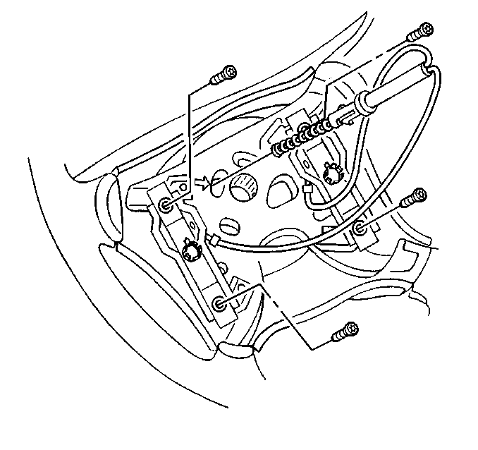
- Remove the steering wheel inflator module. Refer to Steering Wheel Inflator Module Replacement .
- Remove the horn switch assembly. Refer to Horn Switch Replacement - On Vehicle .
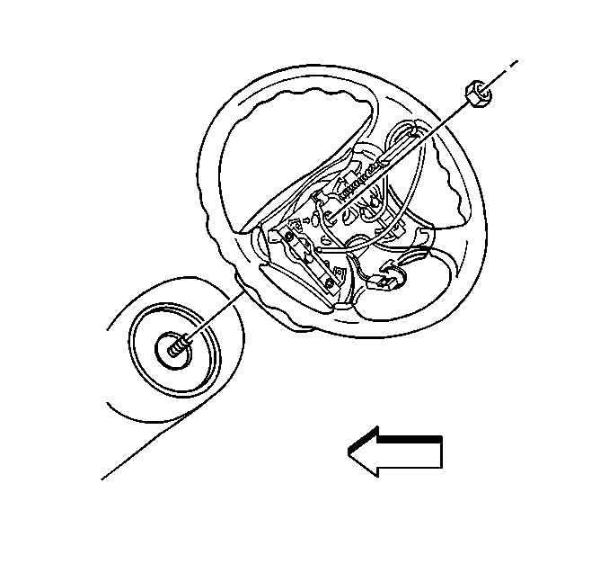
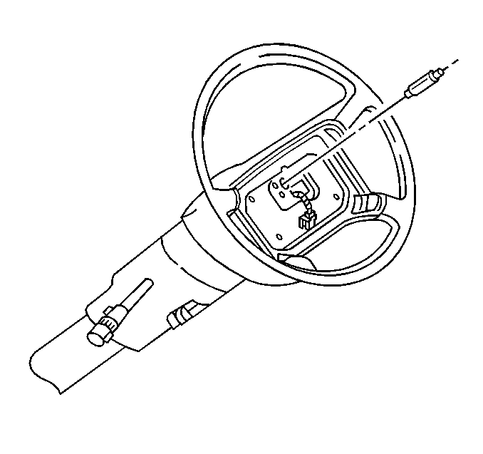
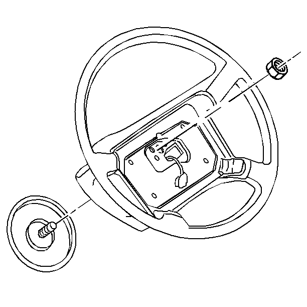
- Remove the steering wheel nut.
- Remove the horn plunger contact from the steering wheel.
- Remove the steering wheel using the J 1859-A .
Caution: Unless directed otherwise, the ignition and start switch must be in the OFF or LOCK position, and all electrical loads must be OFF before servicing any electrical component. Disconnect the negative battery cable to prevent an electrical spark should a tool or equipment come in contact with an exposed electrical terminal. Failure to follow these precautions may result in personal injury and/or damage to the vehicle or its components.
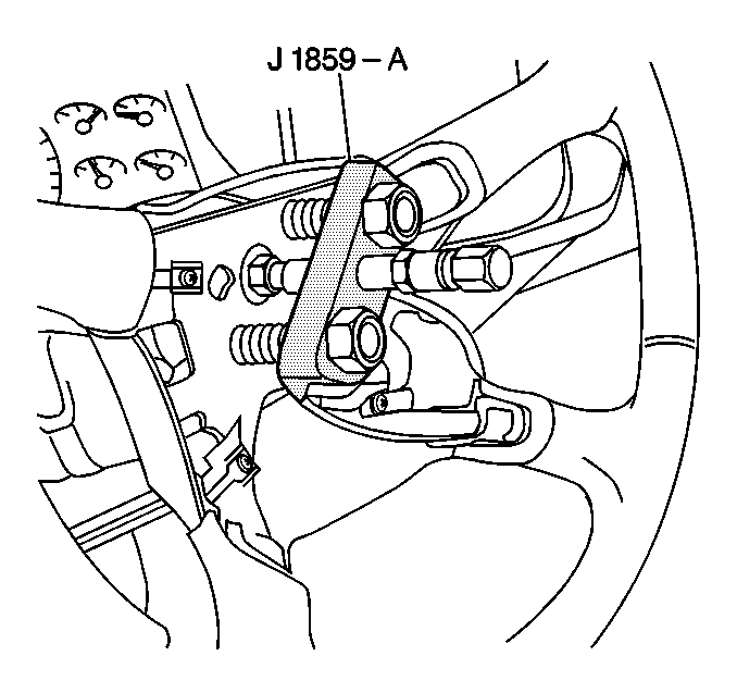
Notice: When removing the steering wheel, use only the specified steering wheel puller. Do not hammer on the end of the steering column shaft. Hammering could loosen the plastic injections which maintain the steering column rigidity.
Important: Note or mark the relationship of the steering wheel splines to the steering shaft.
Installation Procedure
- Align the mark on the steering wheel and steering shaft.
- Install the steering wheel to the steering shaft.
- Install the steering wheel nut.
- Install the horn switch assembly. Refer to Horn Switch Replacement - On Vehicle .
- Install the steering wheel inflator module. Refer to Steering Wheel Inflator Module Replacement .
- Connect the negative battery cable.
Important: Ensure that the turn signal on the multifunction switch is in the neutral position when installing the steering wheel.
Notice: Use the correct fastener in the correct location. Replacement fasteners must be the correct part number for that application. Fasteners requiring replacement or fasteners requiring the use of thread locking compound or sealant are identified in the service procedure. Do not use paints, lubricants, or corrosion inhibitors on fasteners or fastener joint surfaces unless specified. These coatings affect fastener torque and joint clamping force and may damage the fastener. Use the correct tightening sequence and specifications when installing fasteners in order to avoid damage to parts and systems.
Tighten
Tighten the steering wheel nut to 41 N·m (30 lb ft).
Steering Wheel Replacement without RPO CTF
Removal Procedure
Tools Required
J 1859-A Steering Wheel Puller
- Remove the steering wheel inflator module. Refer to Steering Wheel Inflator Module Replacement .
- Remove the steering wheel horn contact.
- Remove the nut that retains the steering wheel to the steering wheel shaft.
- Remove the steering wheel nut.
- Remove the steering wheel using the J 1859-A .
Important: Note or mark the relationship of the steering wheel splines to the steering shaft.
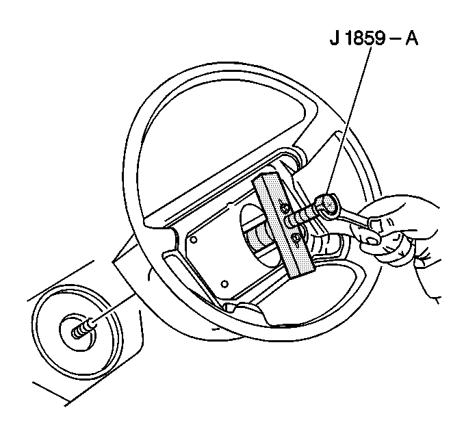
Notice: When removing the steering wheel, use only the specified steering wheel puller. Do not hammer on the end of the steering column shaft. Hammering could loosen the plastic injections which maintain the steering column rigidity.
Installation Procedure
- Align the mark on the steering wheel and steering shaft.
- Install the steering wheel to the shaft.
- Install the nut to the shaft.
- Install the steering wheel horn contact.
- Install the steering wheel inflator module. Refer to Steering Wheel Inflator Module Replacement .
Important: Ensure that the turn signal on the multifunction switch is in the neutral position when installing the steering wheel.
Notice: Use the correct fastener in the correct location. Replacement fasteners must be the correct part number for that application. Fasteners requiring replacement or fasteners requiring the use of thread locking compound or sealant are identified in the service procedure. Do not use paints, lubricants, or corrosion inhibitors on fasteners or fastener joint surfaces unless specified. These coatings affect fastener torque and joint clamping force and may damage the fastener. Use the correct tightening sequence and specifications when installing fasteners in order to avoid damage to parts and systems.
Tighten
Tighten the steering wheel nut to 41 N·m (30 lb ft).
