Removal Procedure
Tools Required
J 42640 Steering Column Anti-Rotation Pin
Notice: The wheels of the vehicle must be straight ahead and the steering column in the LOCK position before disconnecting the steering column or intermediate shaft from the steering gear. Failure to do so will cause the coil assembly in the steering column to become uncentered which will cause damage to the coil assembly.
- Mark the relationships of the intermediate shaft to the following components in order to ensure proper installation:
- Disable the SIR system. Refer to Disabling the SIR System in SIR.
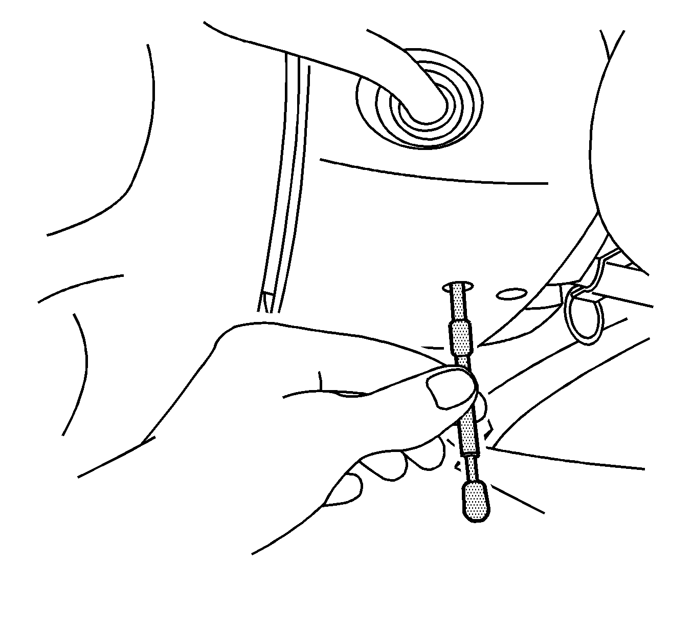
- Install the J 42640 in the steering column lower access hole.
- Remove the upper fan shroud. Refer to Fan Shroud Replacement in Engine Cooling.
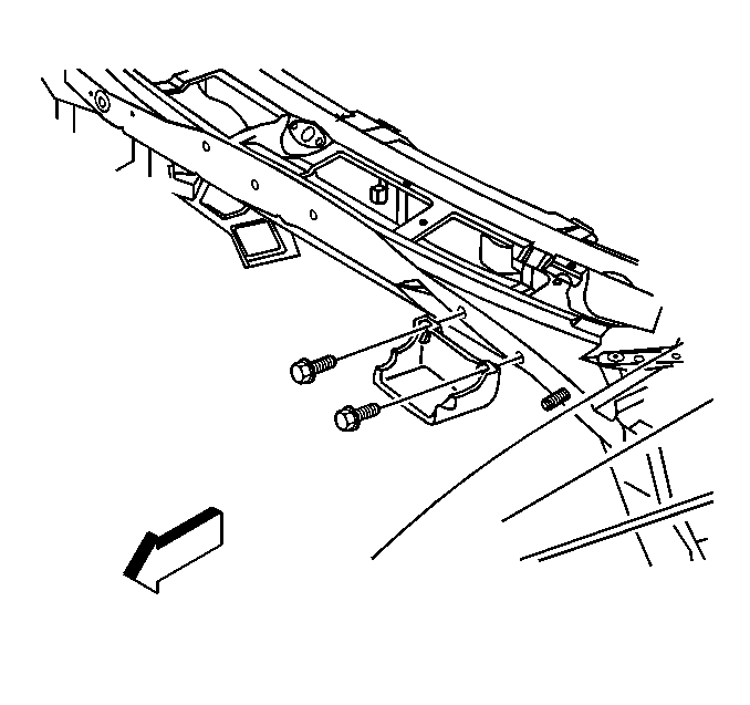
- Remove the bolts from the underhood electrical center and set aside.
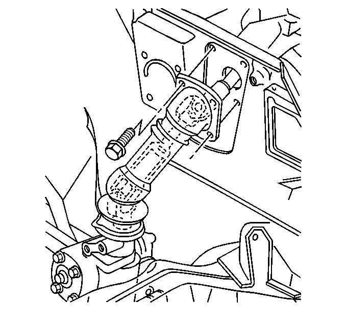
- Remove the intermediate shaft boot from the cowl.
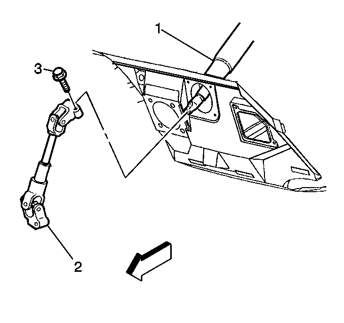
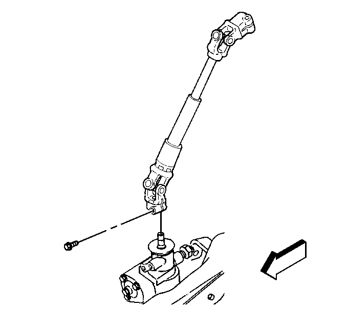
- Remove the pinch bolt (3) from the intermediate shaft (2) at the steering column shaft (1).
- Remove the intermediate shaft boot from the steering gear.
- Remove the intermediate shaft boot from the vehicle.
- Remove the pinch bolt from the intermediate shaft at the steering gear.
- Remove the intermediate shaft.
| • | The steering column shaft |
| • | The steering gear input shaft |
Installation Procedure
- Align the flat on the intermediate shaft with the flat on the steering gear shaft.
- Install the intermediate shaft pinch bolt.
- Install the intermediate shaft boot over the intermediate shaft.
- Align the flat on the intermediate shaft with the flat on the steering column shaft.
- Install the intermediate shaft pinch bolt (3).
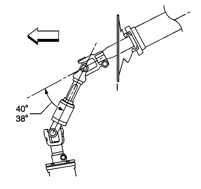
- Measure the intermediate shaft angle. For RWD, the angle must be 38-40 degrees.
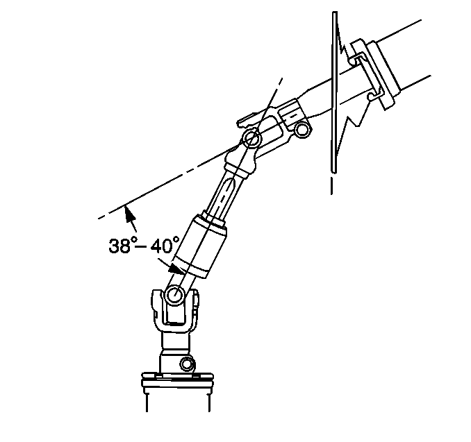
- Measure the intermediate shaft angle. For F4WD, the angle must be 38-40 degrees.
- Install the intermediate shaft boot to the steering gear.
- Install the intermediate shaft boot cowl with the 4 screws.
- Install the underhood electrical center.
- Install the upper fan shroud. Refer to Fan Shroud Replacement in Engine Cooling.
- Remove the J 42640 .
- Enable the SIR system. Refer to Enabling the SIR System in SIR.

Observe the marks that were made before the disassembly.
Install the intermediate shaft to the steering gear shaft.
Notice: Use the correct fastener in the correct location. Replacement fasteners must be the correct part number for that application. Fasteners requiring replacement or fasteners requiring the use of thread locking compound or sealant are identified in the service procedure. Do not use paints, lubricants, or corrosion inhibitors on fasteners or fastener joint surfaces unless specified. These coatings affect fastener torque and joint clamping force and may damage the fastener. Use the correct tightening sequence and specifications when installing fasteners in order to avoid damage to parts and systems.
Tighten
Tighten the intermediate shaft pinch bolt to 41 N·m (30 lb ft).

Do not secure the boot to the steering gear.

Observe the marks that were made before the disassembly.
Install the intermediate shaft (2) to the steering column shaft (1).
Tighten
Tighten the intermediate shaft pinch bolt to 41 N·m (30 lb ft).

Tighten
Tighten the bolts to 5.5 N·m (49 lb in).

