For 1990-2009 cars only
Disassembly Procedure
Tools Required
J 21854-01 Pivot Pin Remover
- Remove the shift lever. Refer to Shift Lever - Disassemble - Off Vehicle .
- Remove the lock module assembly. Refer to Electronic Column Lock Module - Disassemble - Off Vehicle .
- Remove the tilt spring assembly. Refer to Tilt Spring - Disassemble - Off Vehicle .
- Remove the turn signal and multifunction switch assembly. Refer to Turn Signal and Multifunction Switch Assembly - Disassemble - Off Vehicle .
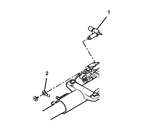
- Remove the automatic transmission shift lock control actuator.
- Use a screwdriver to pry the automatic transmission shift lock control actuator from the steering column jacket assembly.
- Remove the hexagon flanged head bolt.
- Remove the ball and actuator assembly (2).
- Remove the shift lever clevis (1).
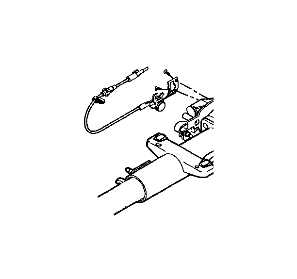
- Remove the 2 oval head 6-lobed socket tapping screws from the shift gate.
- Remove the park lock cable assembly.
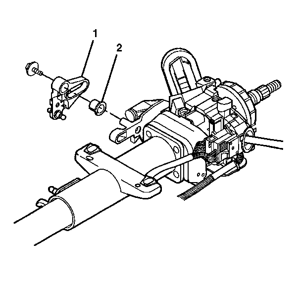
- Remove the hexagon flange head bolt.
- Remove the cable shift cam assembly (1).
- Remove the cam bushing (2) from the cable shift cam assembly (1).
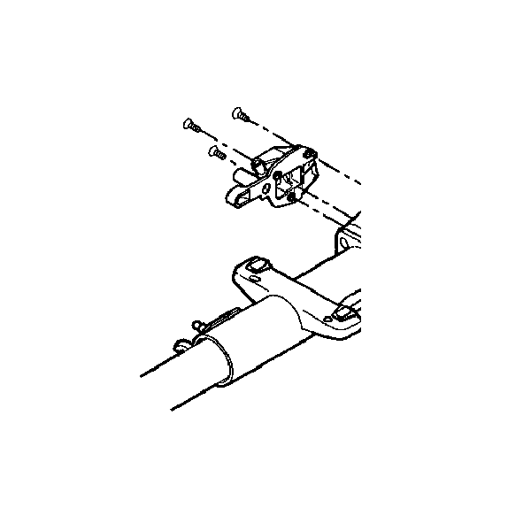
- Remove 3 flat head 6-lobed socket tapping screws.
- Remove the gearshift lever assembly support bracket.
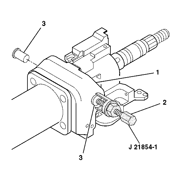
- Remove 2 pivot pins (3) from the steering column support assembly (1) using the J 21854-01 (2).
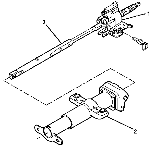
- Remove the tilt head assembly (1) from the steering column jacket (2) with the lower steering shaft (3) still attached.
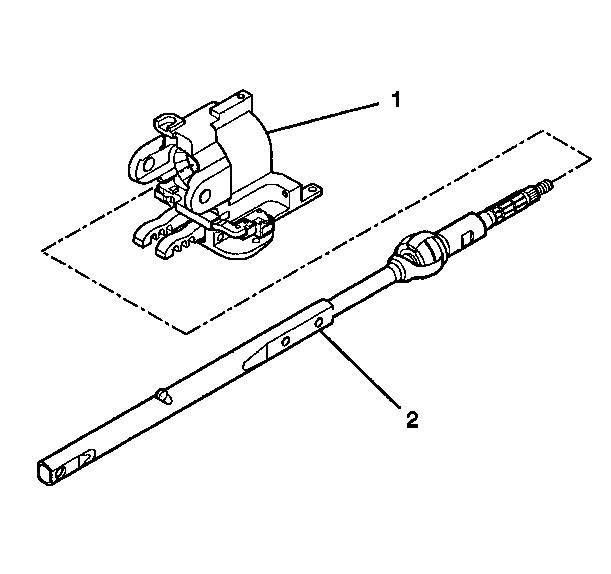
- Remove the tilt head assembly (1) from the steering shaft assembly (2).
- Tilt the race and upper shaft assembly (1) 90 degrees to the lower shaft assembly (2).
- Disengage the race and upper shaft assembly (1) from the lower shaft assembly (2).
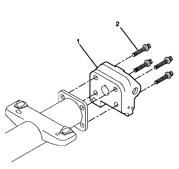
- Remove the 4 TORX® screws (2) from the steering column support assembly (1).
- Remove the steering column seal (3) from the adapter and bearing assembly (2).
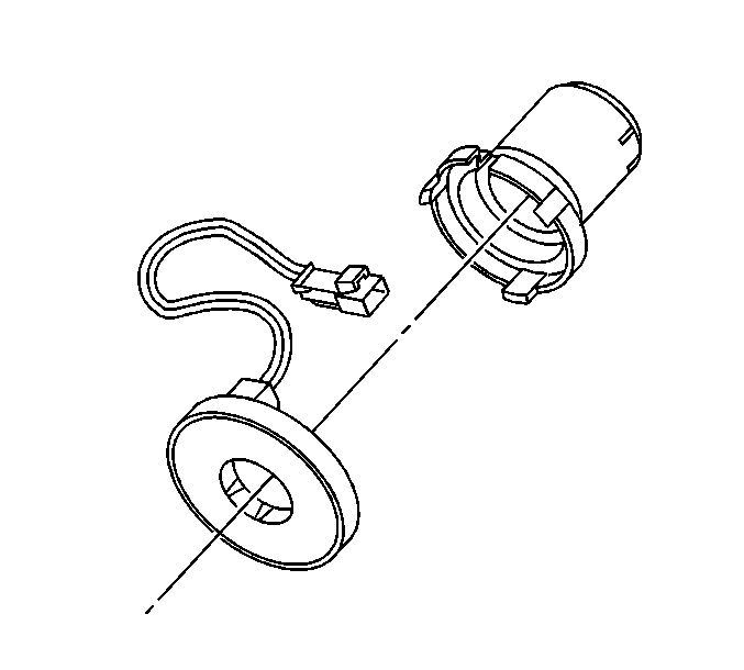
- Remove the EVO sensor assembly from the end of the steering shaft assembly.
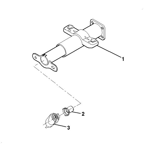
- Remove the adapter and bearing assembly (2) from the jacket assembly (1).
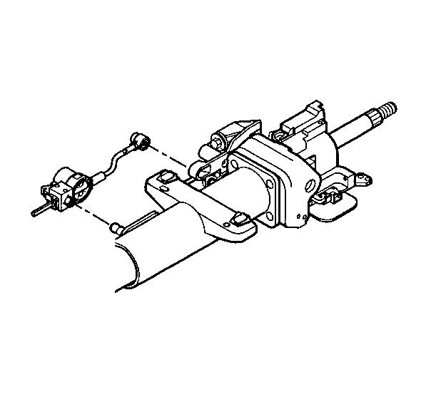
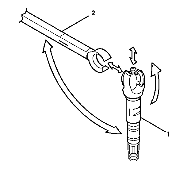
Important: Mark the race and upper shaft assembly and the lower shaft assembly before disassembly. Failure to assemble the race and upper shaft assembly and the lower shaft assembly correctly will cause the steering wheel to be turned 180 degrees.
