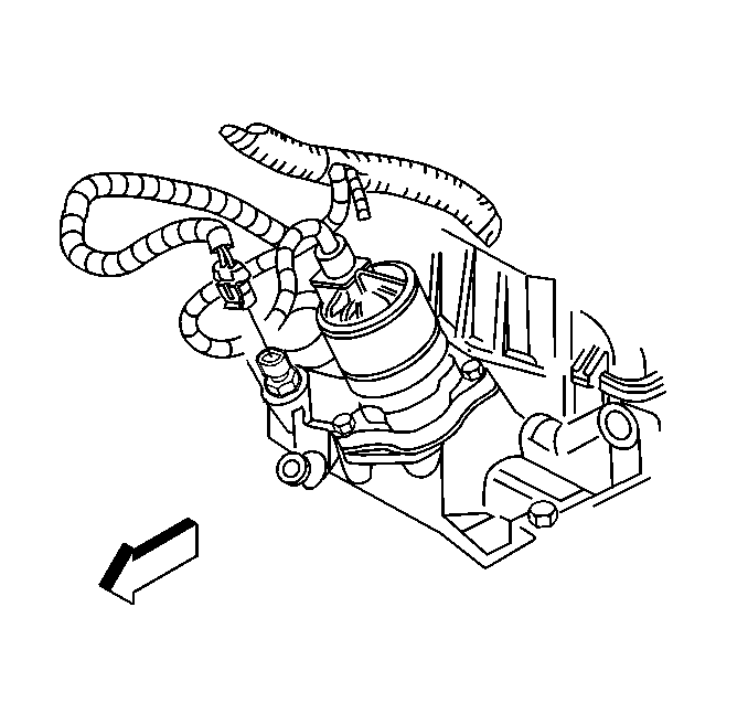
Removal Procedure
Notice: Use care when handling the coolant sensor. Damage to the coolant sensor will affect the operation of the fuel control system.
- Disconnect the negative battery cable.
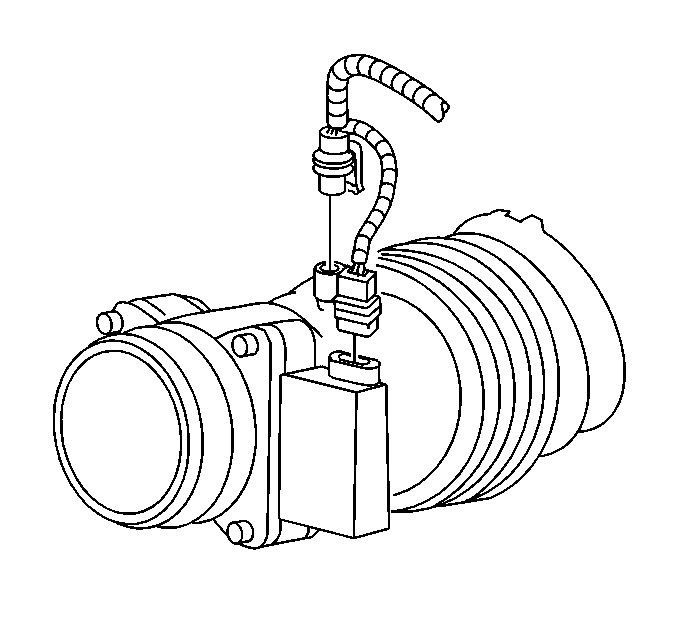
- Disconnect the IAT and MAF sensor harness connectors.
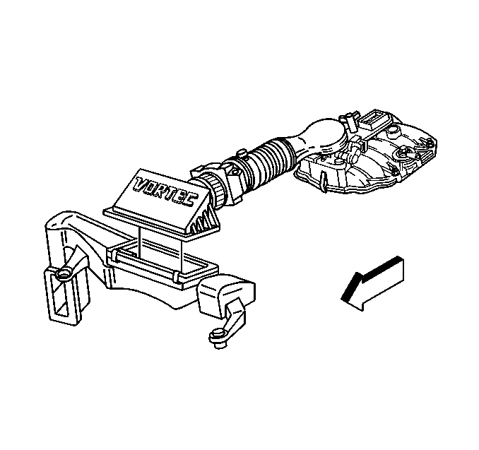
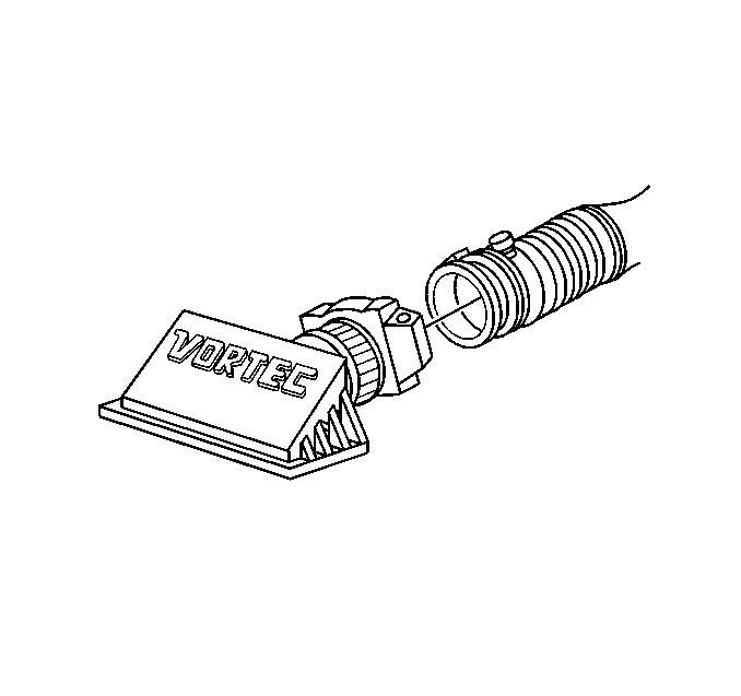
- Remove the air cleaner cover by releasing the retainer clips.
- Remove the air intake tube and MAF sensor by loosening the hose clamp.
- Move the air inlet tube aside.
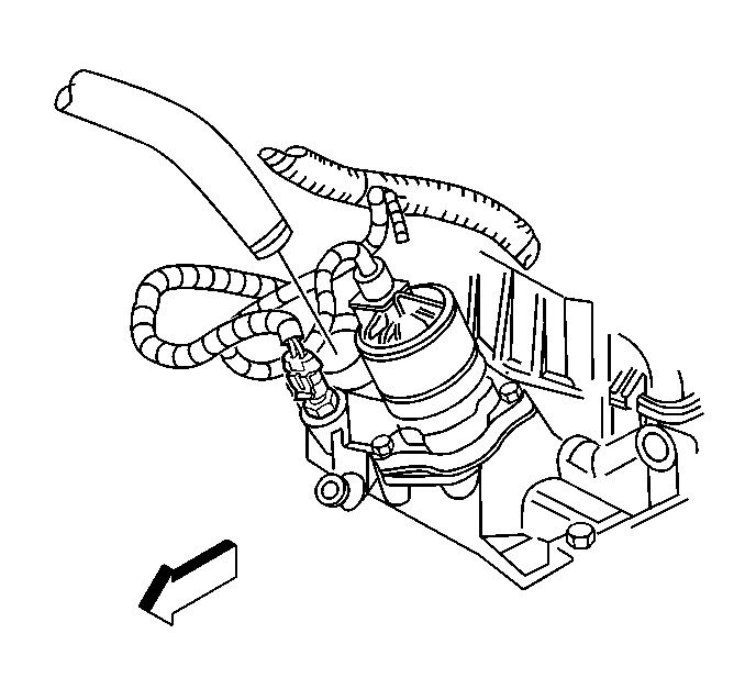
- Relieve the coolant pressure.
- Drain the cooling system below the level of the sensor. Refer to Cooling System Draining and Filling in Engine Cooling.
- Remove the radiator hose from the intake manifold by loosening the radiator hose clamp.
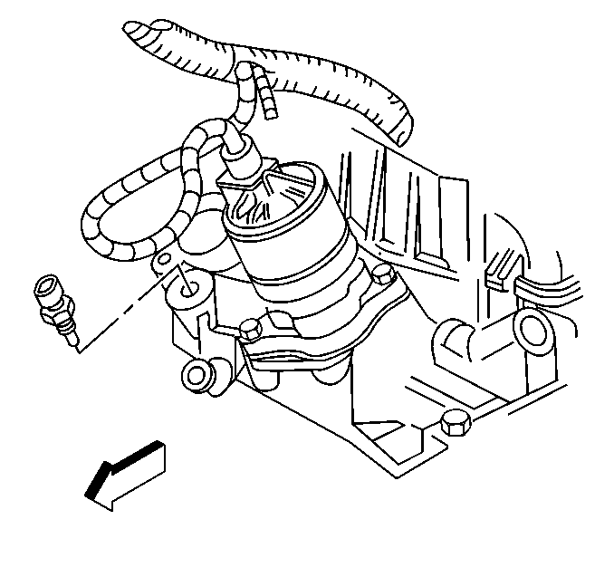
- Disconnect the ECT sensor harness connector.
- Remove the ECT sensor.
Caution: Unless directed otherwise, the ignition and start switch must be in the OFF or LOCK position, and all electrical loads must be OFF before servicing any electrical component. Disconnect the negative battery cable to prevent an electrical spark should a tool or equipment come in contact with an exposed electrical terminal. Failure to follow these precautions may result in personal injury and/or damage to the vehicle or its components.
Caution: To avoid being burned, do not remove the radiator cap or surge tank cap while the engine is hot. The cooling system will release scalding fluid and steam under pressure if radiator cap or surge tank cap is removed while the engine and radiator are still hot.
Installation Procedure
- Coat the ECT threads (only) with sealer P/N 9985253 or equivalent.
- Install the ECT sensor.
- Connect the ECT sensor harness connector.
- Connect the radiator hose.
- Refill the cooling system. Refer to Draining and Filling Cooling System in Engine and Cooling.
- Connect the air cleaner outlet and the MAF sensor.
- Install the air cleaner cover.
- Connect the IAT and MAF sensor harness connectors.
- Connect the negative battery cable.
Notice: Use the correct fastener in the correct location. Replacement fasteners must be the correct part number for that application. Fasteners requiring replacement or fasteners requiring the use of thread locking compound or sealant are identified in the service procedure. Do not use paints, lubricants, or corrosion inhibitors on fasteners or fastener joint surfaces unless specified. These coatings affect fastener torque and joint clamping force and may damage the fastener. Use the correct tightening sequence and specifications when installing fasteners in order to avoid damage to parts and systems.
Tighten
Tighten the sensor to 20 N·m (15 lb ft).
Notice: Use the correct fastener in the correct location. Replacement fasteners must be the correct part number for that application. Fasteners requiring replacement or fasteners requiring the use of thread locking compound or sealant are identified in the service procedure. Do not use paints, lubricants, or corrosion inhibitors on fasteners or fastener joint surfaces unless specified. These coatings affect fastener torque and joint clamping force and may damage the fastener. Use the correct tightening sequence and specifications when installing fasteners in order to avoid damage to parts and systems.
Tighten
Tighten the hose clamp to 4 N·m (30 lb in).
