Steering Shaft, Lower Bearing, and Jacket - Disassemble - Off Vehicle for Chevrolet Astro - 4WD 2002
Steering Shaft, Lower Bearing, and Jacket - Disassemble - Off Vehicle Tilt Column
Tools Required
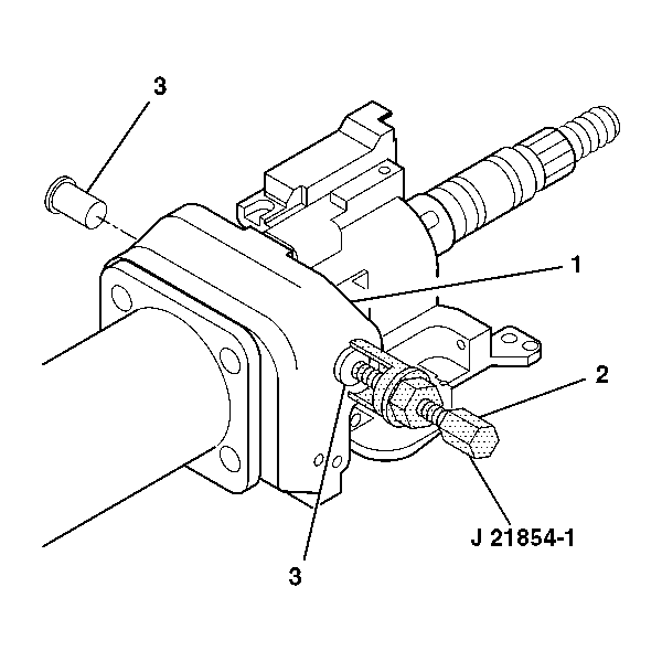
J 21854-01 Pivot Pin Remover

- Disable the inflatable restraint steering wheel module. Refer to Disabling the SIR System in SIR.
- Remove the electronic lock module assembly. Refer to Electronic Column Lock Module - Disassemble - Off Vehicle .
- Remove the shift lever assembly. Refer to Shift Lever - Disassemble - Off Vehicle .
- Remove the turn signal and multifunction switch assembly. Refer to Turn Signal and Multifunction Switch Assembly - Disassemble - Off Vehicle .
- Remove the tilt spring assembly. Refer to Tilt Spring - Disassemble - Off Vehicle .
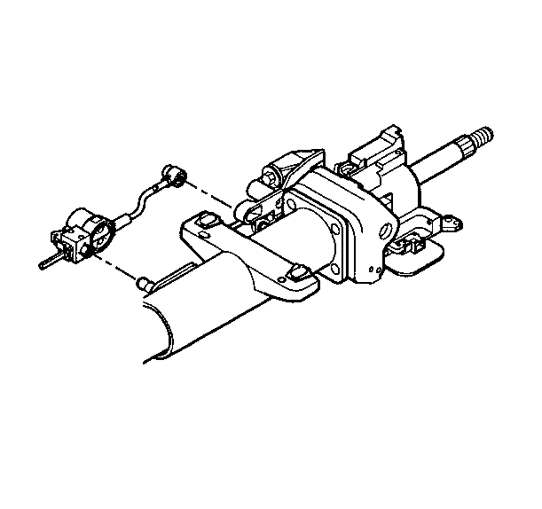
- Use a screwdriver to gently pry the automatic transmission shift lock control from the steering column jacket assembly.
- To break the linear shift assembly down refer to Linear Shift Assembly - Disassemble - Off Vehicle .
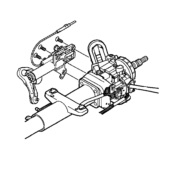
- Remove the 3 TORX® screws from the linear shift assembly.
- Remove the linear shift assembly from the steering column support assembly.
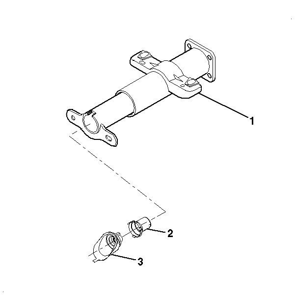
- Remove the steering column seal (3) from the adapter and bearing assembly (2).
- Remove the adapter and bearing assembly (2) from the steering column jacket assembly (1).
- Remove the 2 pivot pins (3) from the steering column support assembly (1) using J 21854-01 (2).
- Remove the tilt head assembly (1) from the steering column jacket assembly (2) with the lower steering shaft (3) still attached.
- Remove the tilt head assembly (1) from the steering shaft assembly (2).
- Tilt the race and upper shaft assembly (1) 90 degrees to the lower shaft assembly (2).
- Disengage the race and upper shaft assembly (1) from the lower shaft assembly (2).
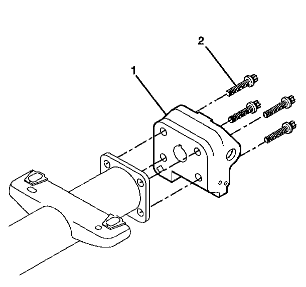
- Remove the 4 TORX® screws (2) from the steering column support assembly (1).
- Remove the steering column support assembly (1) from the steering column jacket assembly.
Caution: This vehicle is equipped with a Supplemental Inflatable Restraint (SIR) System. Failure to follow the correct procedure could cause the following conditions:
• Air bag deployment • Personal injury • Unnecessary SIR system repairs • Refer to SIR Component Views in order to determine if you are performing service on or near the SIR components or the SIR wiring. • If you are performing service on or near the SIR components or the SIR wiring, disable the SIR system. Refer to Disabling the SIR System.
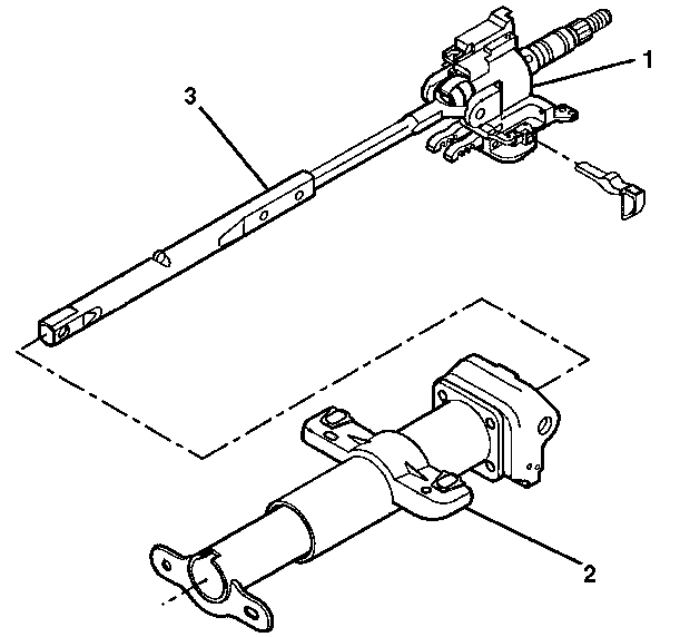
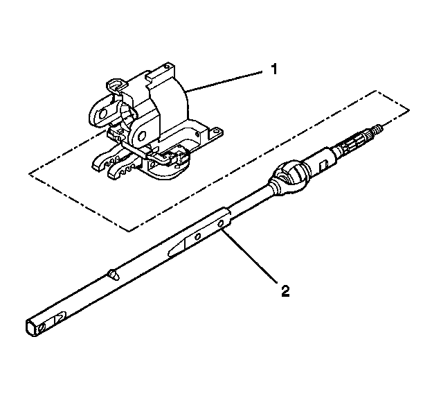
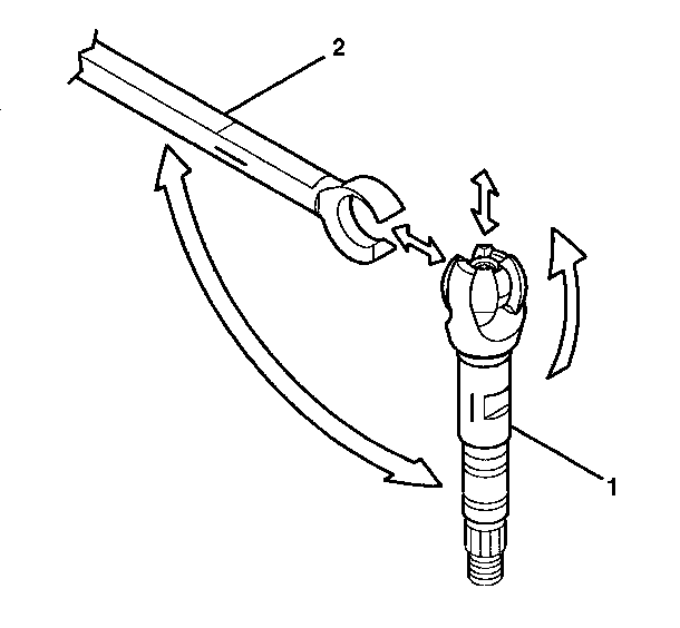
Important: Mark the race and upper shaft assembly and the lower shaft assembly before disassembly. Failure to assemble the race and upper shaft assembly and the lower shaft assembly correctly will cause the steering wheel to be turned 180 degrees.
Steering Shaft, Lower Bearing, and Jacket - Disassemble - Off Vehicle Standard Column
- Disable the inflatable restraint steering wheel module. Refer to Disabling the SIR System in SIR.
- Remove the electronic lock module assembly. Refer to Electronic Column Lock Module - Disassemble - Off Vehicle .
- Remove the shift lever assembly. Refer to Shift Lever - Disassemble - Off Vehicle .
- Remove the turn signal and multifunction switch assembly. Refer to Turn Signal and Multifunction Switch Assembly - Disassemble - Off Vehicle .
- Use a screwdriver to gently pry the automatic transmission shift lock control from the steering column jacket assembly.
- Remove the 3 flat head 6-lobed socket tapping screws.
- Remove the park lock cable assembly.
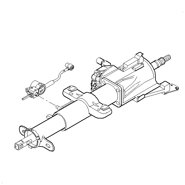
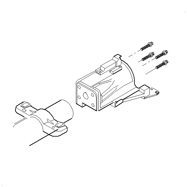
- Remove the 4 TORX® screws from the steering column housing assembly.
- Remove the steering column housing assembly from the steering column housing jacket.
- Remove the following parts from the steering column jacket assembly:
Caution: This vehicle is equipped with a Supplemental Inflatable Restraint (SIR) System. Failure to follow the correct procedure could cause the following conditions:
• Air bag deployment • Personal injury • Unnecessary SIR system repairs • Refer to SIR Component Views in order to determine if you are performing service on or near the SIR components or the SIR wiring. • If you are performing service on or near the SIR components or the SIR wiring, disable the SIR system. Refer to Disabling the SIR System.
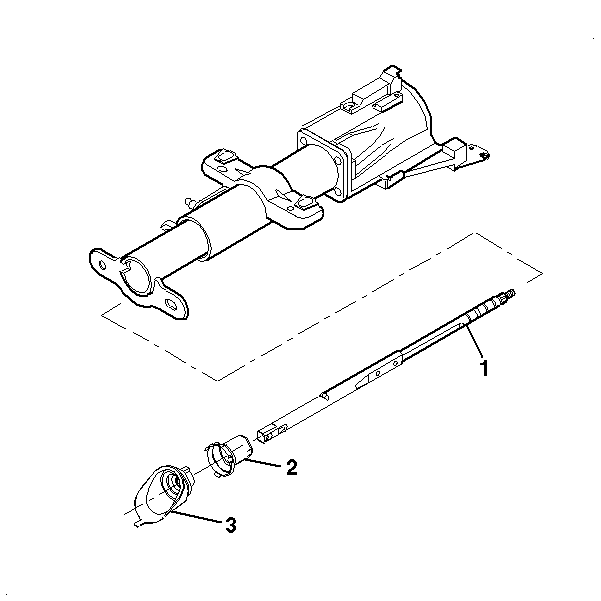
| 10.1. | The steering column seal (3). |
| 10.2. | The adapter and bearing assembly (2). |
| 10.3. | The lower steering shaft (1). |
