Ignition Lock Cylinder Case Replacement Tilt Column
Removal Procedure
Caution: Refer to SIR Caution in the Preface section.
- Disable the SIR system. Refer to
SIR Disabling and Enabling
in SIR.
- Remove the steering wheel from the steering column. Refer to
Steering Wheel Replacement
.
- Remove the turn signal cancel cam. Refer to
Turn Signal Cancel Cam and Upper Bearing Thrust Washer
.
- Remove the ignition lock cylinder. Refer to
Ignition Lock Cylinder Replacement
.
- Remove the ignition switch only. Refer to
Ignition and Start Switch Replacement
.
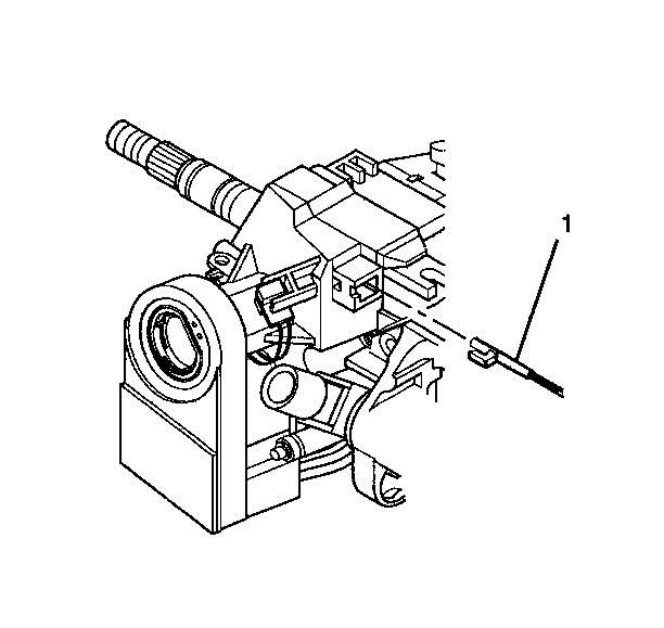
- Remove the park lock cable assembly (1) from the ignition
lock cylinder case.
| 6.1. | Place the steering column lock cylinder set into the OFF position. |
| 6.2. | Place the shift lever clevis into the PARK position. |
| 6.3. | Use a small blade to push against the locking tab on the end of
the park lock cable assembly (1). |
| 6.4. | Disconnect the park lock cable assembly (1) from the ignition
lock cylinder case. |
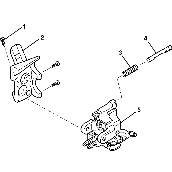
- Remove the 3 pan
head tapping screws (1) from the ignition lock cylinder case (2).
Important: The lock bolt assembly (4) is under slight spring tension from
the lock bolt spring (3). Hold the lock bolt (4) in place while
removing the ignition lock cylinder case (2).
- Remove the ignition lock cylinder case (2) and the lock bolt
assembly (4) from the steering column tilt head assembly (5).
- Remove the lock bolt spring (3) from the lock bolt assembly (4).
Installation Procedure
- Install the lock bolt
spring (3) into the steering column tilt head assembly (5).
- Position the cutout in the lock bolt assembly (4) at the
6 o'clock position.
- Install the lock bolt assembly (4) into the steering column
tilt head assembly (5).
- Push the lock bolt assembly (4) into the steering column
tilt head assembly (5) until the lock bolt assembly is flush with the
steering column tilt head assembly (5).
- Align the ignition lock cylinder case (2) with the steering
column tilt head assembly (5).
Notice: Refer to Fastener Notice in the Preface section.
- Screw the 3 pan head tapping screws (1) into the ignition
lock cylinder case (2).
Tighten
Tighten the screws to 7 N·m (62 lb in).
Caution: Improper routing of the wire harness assembly may damage the inflatable
restraint steering wheel module coil. This may result in a malfunction of
the coil, which may cause personal injury.
- Place steering column lock cylinder set into the OFF position.
- Place the shift lever clevis into the PARK position.
- Press the locking tab on the end of the park lock cable assembly (1)
into the slot in the ignition lock cylinder case.
- Install the ignition switch only. Refer to
Ignition and Start Switch Replacement
.
- Install the ignition lock cylinder. Refer to
Ignition Lock Cylinder Replacement
.
- Install the turn signal cancel cam. Refer to
Turn Signal Cancel Cam and Upper Bearing Thrust Washer
.
- Install the steering wheel to the steering column. Refer to
Steering Wheel Replacement
.
- Enable the SIR system. Refer to
SIR Disabling and Enabling
in SIR.
Ignition Lock Cylinder Case Replacement Standard Column
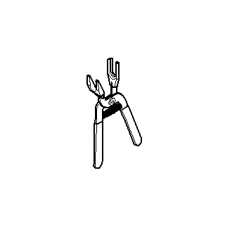
Tools Required
J 41396 Park Lock
Cable Pliers
Removal Procedure
Caution: Refer to SIR Caution in the Preface section.
- Disable the SIR system. Refer to
SIR Disabling and Enabling
in SIR.
- Remove the ignition lock cylinder. Refer to
Ignition Lock Cylinder Replacement
.
- Remove the steering column tilt head housing. Refer to
Steering Column Tilt Head Housing Replacement
.
- Remove the ignition switch only. Refer to
Ignition and Start Switch Replacement
.
- Remove the park lock cable assembly (1) from the ignition
lock cylinder case.
| 5.1. | Place the lock cylinder in the OFF-LOCK position. |
| 5.2. | Place the shift lever clevis into the PARK position. |
| 5.3. | Insert a small screwdriver into the slot on the ignition lock
cylinder case. Push against the locking tab on the end of the park lock cable
assembly (1). |
| 5.4. | Disconnect the park lock cable assembly (1) from the ignition
lock cylinder case. |
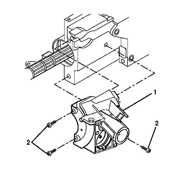
- Remove the 3 pan
head tapping screws (2) from the ignition lock cylinder case (1).
- Remove the ignition lock cylinder case (1) from the steering
column housing assembly.
Installation Procedure
Notice: Refer to Fastener Notice in the Preface section.
- Install the ignition lock
cylinder case (1) onto the steering column housing assembly.
- Screw the 3 pan head tapping screws (2) into the ignition
lock cylinder case.
Tighten
Tighten the pan head tapping screws to 7 N·m (62 lb in).
Caution: Improper routing of the wire harness assembly may damage the inflatable
restraint steering wheel module coil. This may result in a malfunction of
the coil, which may cause personal injury.
- Connect the park lock cable assembly (1).
| • | Place the lock cylinder in the OFF-LOCK position. |
| • | Place the gear shift lever clevis into the PARK position. |
| • | Press the locking tab on the end of the park lock cable assembly (1)
into the slot in the ignition lock cylinder case. |
- Install the ignition switch . Refer to
Ignition and Start Switch Replacement
.
- Install the steering column tilt head housing. Refer to
Steering Column Tilt Head Housing Replacement
.
- Install the ignition lock cylinder. Refer to
Ignition Lock Cylinder Replacement
.
- Enable the SIR system. Refer to
SIR Disabling and Enabling
in SIR.
