Wheel Speed Sensor Replacement RWD
Removal Procedure
- Raise and support the vehicle. Refer to Lifting and Jacking the Vehicle in General Information.
- Remove the tire and wheel. Refer to Tire and Wheel Removal and Installation in Tires and Wheels.
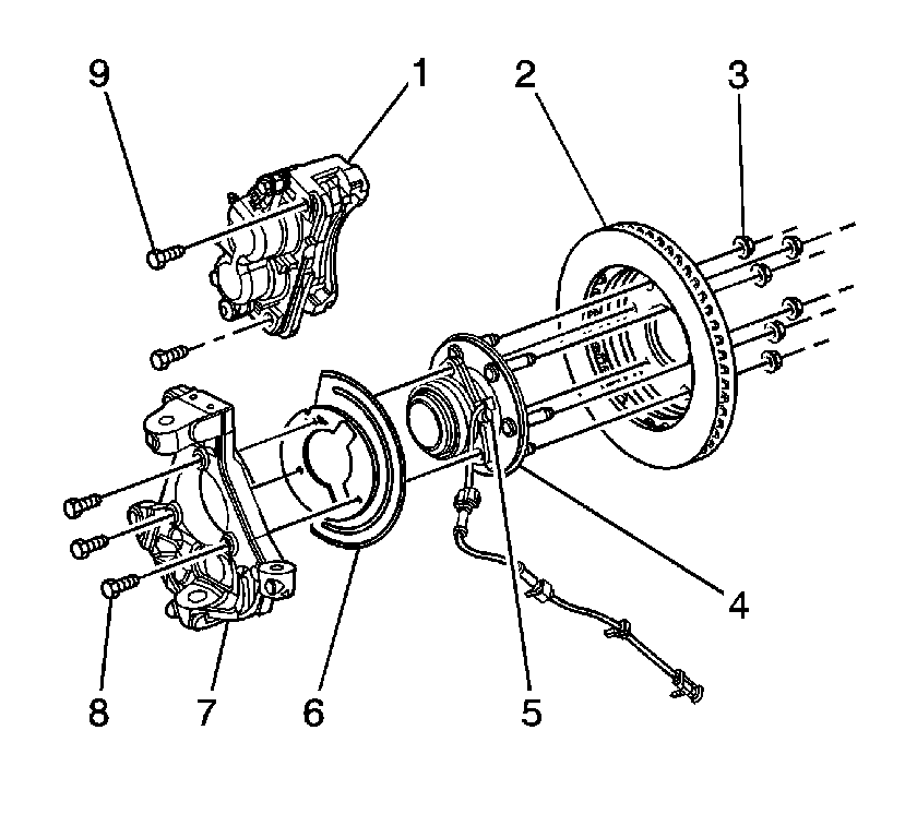
- Remove the brake rotor (2). Refer to Front Brake Rotor Replacement in Disc Brakes.
- Remove the wheel speed sensor (WSS) mounting bolt.
- Remove the wheel speed sensor (5) from the hub/bearing assembly (4).
- Remove the WSS cable mounting clip from the knuckle.
- Remove the WSS cable mounting clip from the upper control arm.
- Remove the WSS cable mounting clip from the frame attachment point.
- Remove the WSS cable electrical connector.

Important: The wheel speed sensor mounts to the hub/bearing assembly. Thoroughly clean around this area in order to prevent any dirt or contaminants from entering the sealed wheel bearing. Failure to do this may lead to premature wheel bearing failure.
NOTICE: Carefully remove the sensor by pulling it straight out of the bore. DO NOT use a screwdriver, or other device to pry the sensor out of the bore. Prying will cause the sensor body to break off in the bore.
Installation Procedure
- Plug the WSS bore to prevent debris from falling into the hub.
- Using a wire brush or equivalent, clean the WSS mounting surface on the hub to remove any rust or corrosion.
- Apply a thin layer of wheel bearing lubricant, GM P/N 01051344 to the hub surface and the sensor O-ring prior to the sensor installation.
- Install the WSS (5) into the hub/bearing assembly (4).
- Install the WSS mounting bolt.
- Install the WSS cable mounting clip to the knuckle.
- Install the WSS cable mounting clip to the upper control arm.
- Install the WSS cable mounting clip to the frame attachment point.
- Connect the WSS cable electrical connector.
- Install the brake rotor (2). Refer to Front Brake Rotor Replacement in Disc Brakes.
- Install the tire and wheel. Refer to Tire and Wheel Removal and Installation in Tires and Wheels.
- Return to Diagnostic Starting Point - Antilock Brake System .

Notice: Refer to Fastener Notice in the Preface section.
Tighten
Tighten the WSS mounting bolt to 18 N·m
(13 lb ft).
Wheel Speed Sensor Replacement A4WD
Removal Procedure
- Raise and support the vehicle. Refer to Lifting and Jacking the Vehicle in General Information.
- Remove the tire and wheel. Refer to Tire and Wheel Removal and Installation in Tires and Wheels.
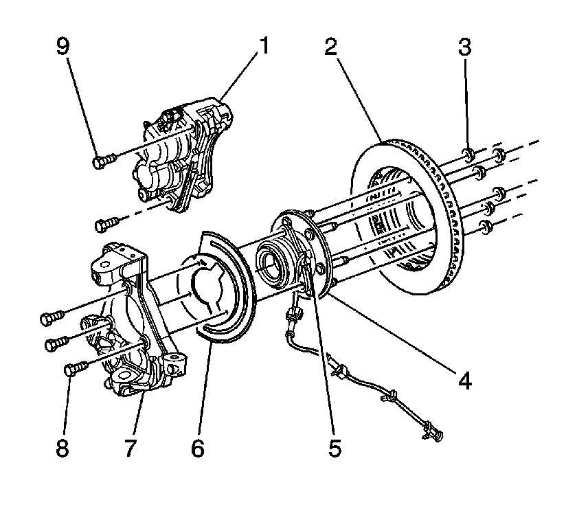
- Remove the brake rotor (2). Refer to Front Brake Rotor Replacement in Disc Brakes.
- Remove the wheel speed sensor (WSS) mounting bolt.
- Remove the wheel speed sensor (5) from the hub/bearing assembly (4).
- Remove the WSS cable mounting clip from the knuckle.
- Remove the WSS cable mounting clip from the upper control arm.
- Remove the WSS cable mounting clip from the frame attachment point.
- Remove the WSS cable electrical connector.

Important: The wheel speed sensor mounts to the hub/bearing assembly. Thoroughly clean around this area in order to prevent any dirt or contaminants from entering the sealed wheel bearing. Failure to do this may lead to premature wheel bearing failure.
NOTICE: Carefully remove the sensor by pulling it straight out of the bore. DO NOT use a screwdriver, or other device to pry the sensor out of the bore. Prying will cause the sensor body to break off in the bore.
Installation Procedure
- Plug the WSS bore to prevent debris from falling into the hub.
- Using a wire brush or equivalent, clean the WSS mounting surface on the hub to remove any rust or corrosion.
- Apply a thin layer of wheel bearing lubricant, GM P/N 01051344 to the hub surface and the sensor O-ring prior to the sensor installation.
- Install the WSS (5) into the hub/bearing assembly (4).
- Install the WSS mounting bolt.
- Install the WSS cable mounting clip to the knuckle.
- Install the WSS cable mounting clip to the upper control arm.
- Install the WSS cable mounting clip to the frame attachment point.
- Connect the WSS cable electrical connector.
- Install the brake rotor (2). Refer to Front Brake Rotor Replacement in Disc Brakes.
- Install the tire and wheel. Refer to Tire and Wheel Removal and Installation in Tires and Wheels.
- Return to Diagnostic Starting Point - Antilock Brake System .

Notice: Refer to Fastener Notice in the Preface section.
Tighten
Tighten the WSS mounting bolt to 18 N·m
(13 lb ft).
