For 1990-2009 cars only
Control Valve Body Disassemble
Tools Required
J 33163 Valve Tray Set
- Position the control valve module on the work table so that the main valve body module is facing up.
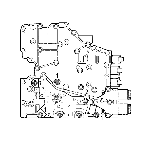
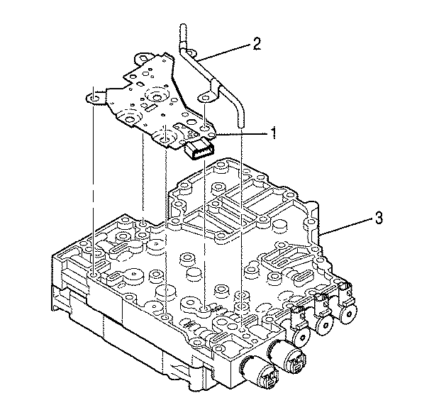
- Remove six bolts (1) and one bolt (2) retaining the reverse signal tube and pressure switch assembly to the main valve body.
- Remove reverse signal tube (2) from main valve body (3).
- Remove pressure switch assembly (1) from main valve body (3).
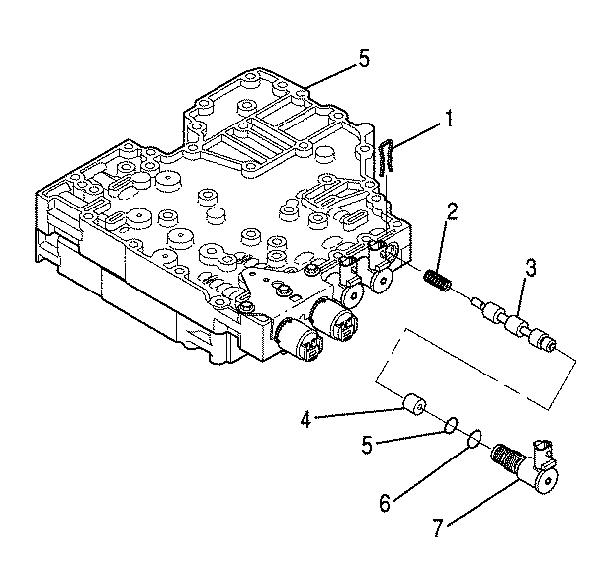
- Remove F trim solenoid retainer (1).
- Remove F trim solenoid (7), sleeve (4), valve (3), and spring (2).
- Remove O-rings (5) and (6) from F trim solenoid (7).
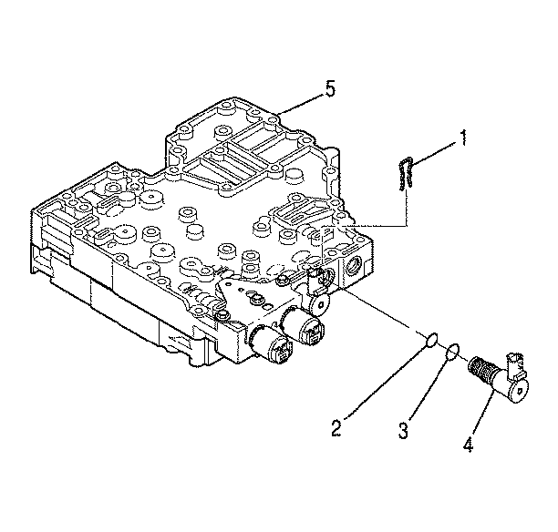
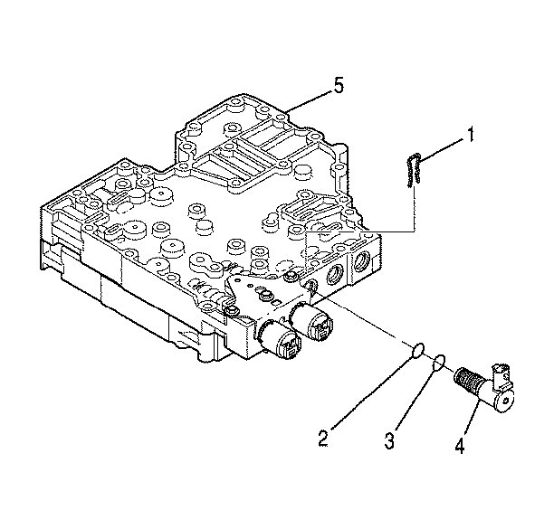
- Remove D ON/OFF shift solenoid retainer (1).
- Remove D ON/OFF shift solenoid (4).
- Remove O-rings (2) and (3) from D ON/OFF shift solenoid (4).
- Remove E ON/OFF shift solenoid retainer (1).
- Remove E ON/OFF shift solenoid (4).
- Remove O-rings (2) and (3) from E ON/OFF shift solenoid (4).
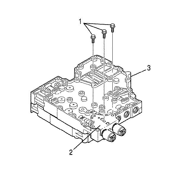
- Remove three bolts (1) that retain A/B solenoid bracket (2) to main valve body (3).
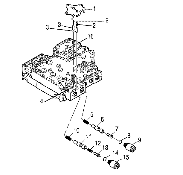
- Remove A/B solenoid bracket (1), two accumulator springs (2), and two accumulator plugs (3).
- Remove A trim solenoid (15), valve (13), spring (12), if present, valve (11), and spring (10).
- Remove B trim solenoid (9), valve (7), valve (6), and spring (5).
- Remove O-ring (14) from A trim solenoid (15).
- Remove O-ring (8) from B trim solenoid (9).
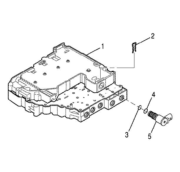
- Position the control valve module on the work table so that shift valve body (1) is facing up.
- Remove C ON/OFF shift solenoid retainer (2).
- Remove C ON/OFF shift solenoid (5).
- Remove O-rings (3) and (4) from C ON/OFF shift solenoid (5).
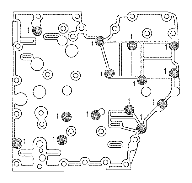
- Position the control valve module on the work table so that the main valve body is facing up. Reinstall four bolts (1) so that the bolts are partially threaded into the shift valve body and protrude from the main valve body.
- Remove fourteen bolts (1) retaining the shift valve body and the main valve body together.
- Position the control valve module on edge so that the top and bottom are vertical.
- Gently tap the bolts until the module separates.
- Position the control valve assembly on the work table so that shift valve body (1) is facing up.
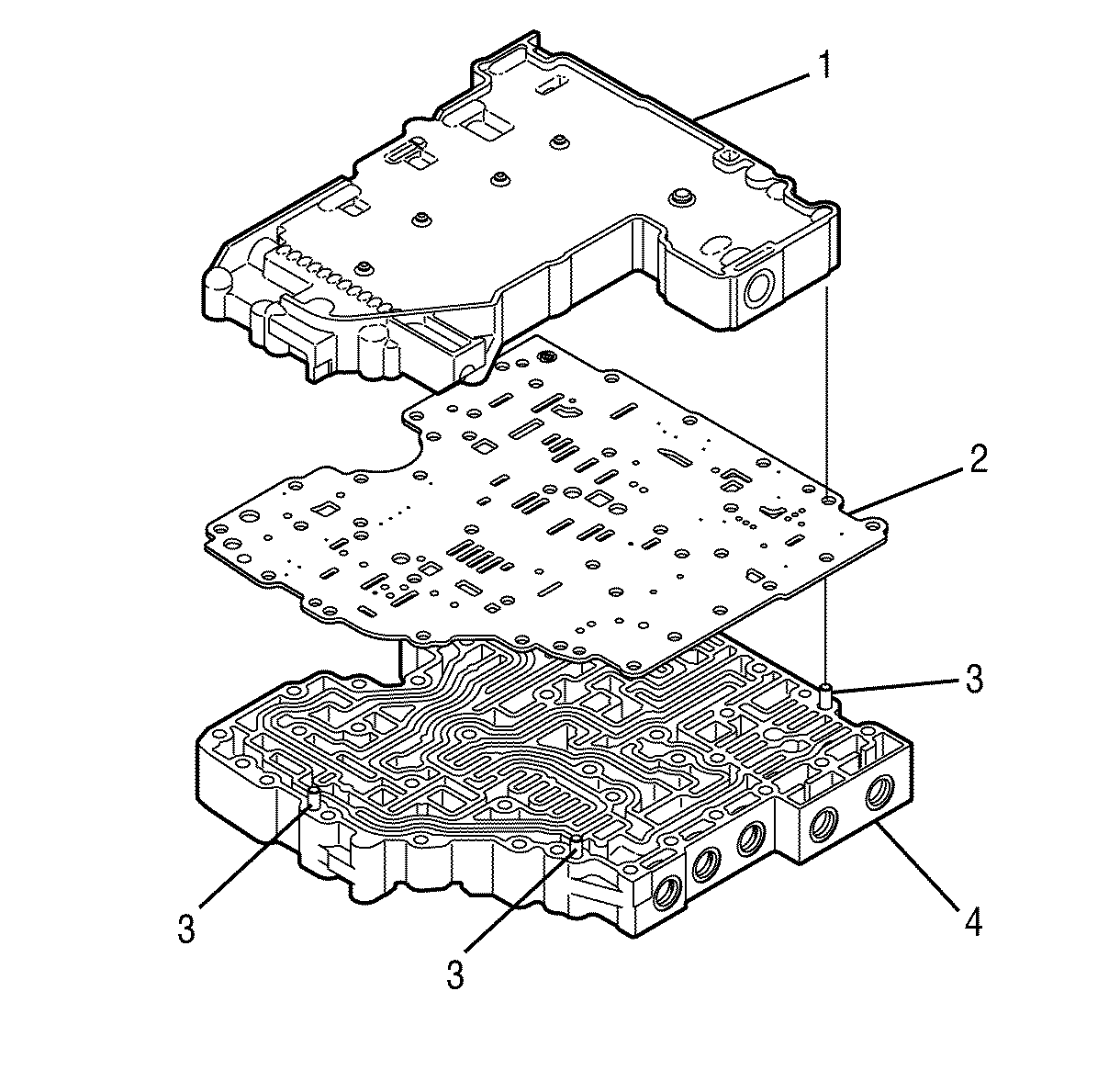
- Separate shift valve body assembly (1), separator plate (2), and main valve body assembly (4).
Control Valve Body Clean and Inspect
Tools Required
Valve Tray Set
Notice:
• Transmission damage may occur when control valve assembly springs and
other parts are mistakenly interchanged. Interchanging parts can be avoided by observing
the following precautions: - Tag each part as it is removed. - Use Valve Tray Set to organize parts and to simplify correct valve body
reassembly. • Protect control valve assembly parts from damage by observing the following
precautions: - Handle all valves carefully. - Protect control valve assembly parts during removal, cleaning, inspection,
and reassembly. - Keep the parts in a clean container until the parts are installed.
- Clean all removed parts with volatile mineral spirits or other similar cleaning agent.
- Clean fluid passages by working a piece of soft wire through the passage and flushing with mineral spirits. Dry the passages with compressed air.
- Inspect valves for wear, nicks, or scratches. Remove minor imperfections with a soft stone or crocus cloth. Replace any damaged valves.
- Inspect springs for signs of overheating, permanent set, or wear. Replace suspect springs.
- Inspect mating surfaces for nicks, burrs, scratches, or foreign matter. Remove any defects with crocus cloth or a soft stone. Replace damaged parts.
- Inspect bores for wear, scratches, and grooves. Remove scratches and burrs with crocus cloth. Replace deeply grooved or scratched parts.
- Inspect threaded parts for burred or damaged threads. Remove burrs with a soft stone or fine file.
- Inspect threaded openings for damaged threads. Correct damaged threads with a correctly sized tap.

