Tools Required
| • | J 24204-2 Bar and Stud Assembly |
| • | J 36850 Transjel® Lubricant |
| • | J 44530 3rd, 5th, and Reverse Clutch / 2nd Clutch Piston Spring Compressor |
- Position the transmission case so that the rear of the case is facing up.
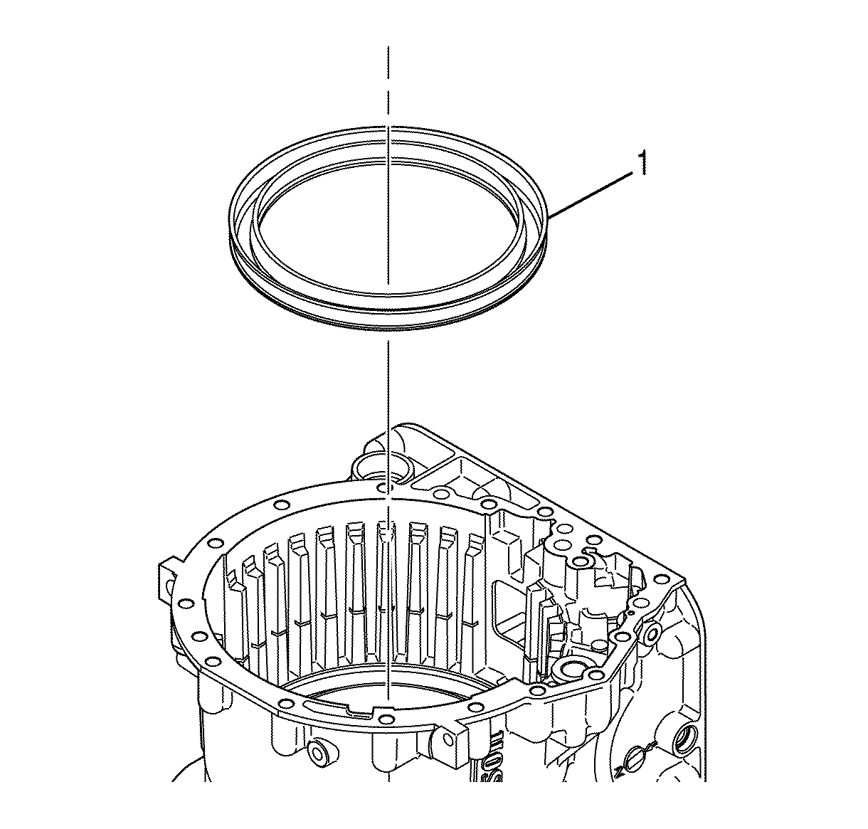
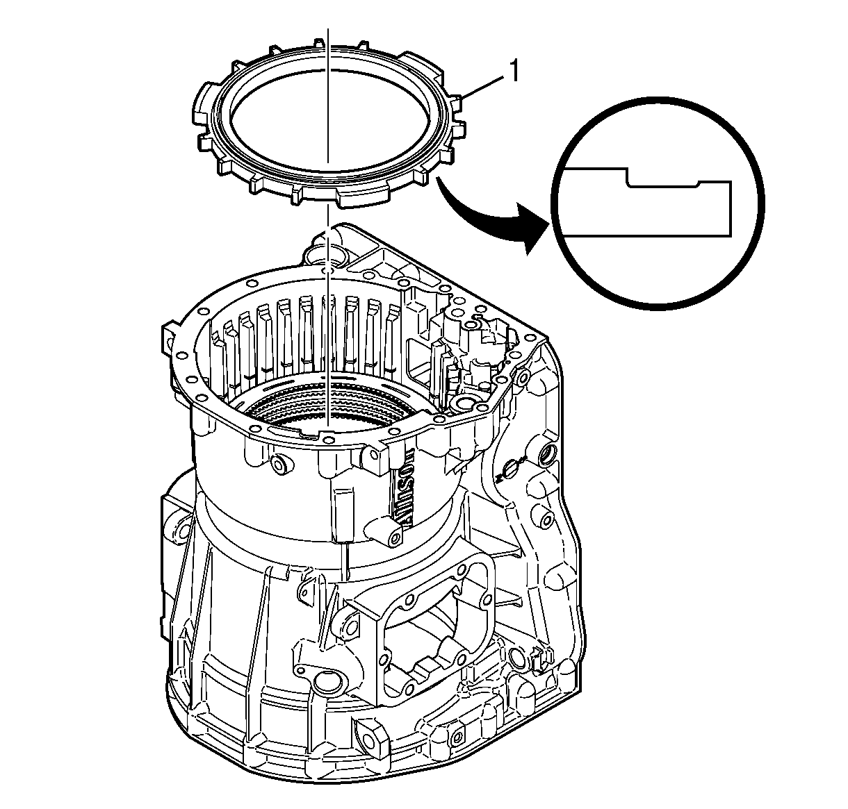
- Apply J 36850 or an equivalent lubricant to the inside and outside diameters of the new 2nd clutch piston assembly (1).
- Align the new 2nd clutch piston assembly (1) so that the seal is facing down and the 1.016 mm (0.040 in) lubrication/cooling orifice is positioned at the top of the transmission case.
- Install the 2nd clutch piston assembly (1).
- Gently tap the piston until the piston seats.
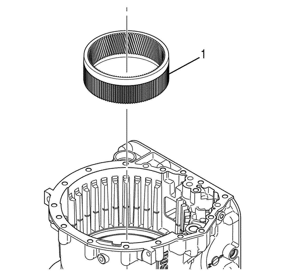
- Align the input internal ring gear (1) so that the outside splines are facing down.
- Install the input internal ring gear (1).
- Rotate the ring gear until the 3rd, 5th, and reverse fiber plates are engaged.
- Make sure the input internal ring gear (1) is seated against the thrust plates of the 3rd, 5th, and reverse clutch backing plate assembly.
- Install the input carrier module (2).
- Rotate the input carrier module until the module drops into place.
- Align the thrust bearing (1) so that the blue stripe on the thrust bearing is facing away from the input carrier module (2).
- Install the thrust bearing (1) onto the input carrier module (2).
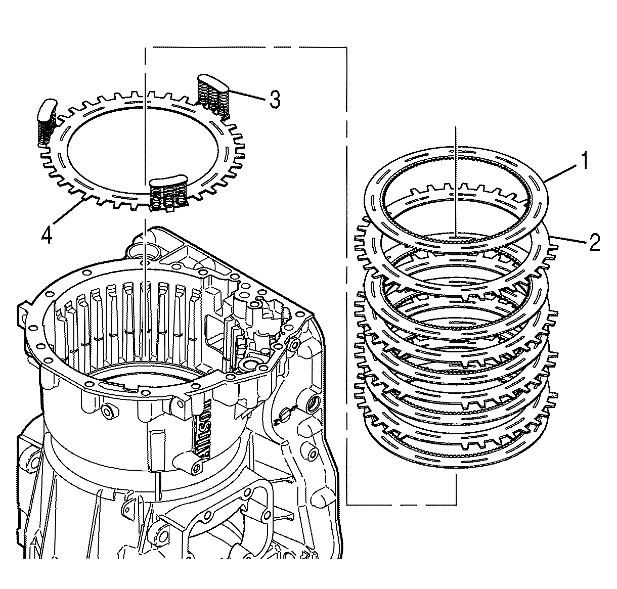
- Install 3 piston return spring assemblies (1) onto the 2nd spring plate (2).
- Align the 2nd clutch spring plate (4) and the piston return spring assemblies (3) with the spring assemblies up.
- Install the spring plate (4) into the transmission case.
- Starting with a 2nd clutch fiber plate, alternately install five 2nd clutch fiber plates (1) and four 2nd clutch steel plates (2).
- Install the 2nd clutch backing plate (1).
- The threaded rod of J 24204-2 must pass through but not touch the bushing.
- Install J 24204-2 (1) and J 44530 (2) into the transmission case.
- Make sure J 24204-2 does not touch the gear thrust plate rivets (6) on the 3rd, 5th, and reverse clutch backing plate assembly.
- Compress the piston return spring assemblies (5) until the retaining ring groove is visible.
- Install the 2nd clutch retaining ring (4).
- Install the low and reverse clutch retaining ring (3) with the retaining ring gap 180 degrees from the 2nd clutch retaining ring gap.
- Remove J 24204-2 and J 44530 from the transmission case.
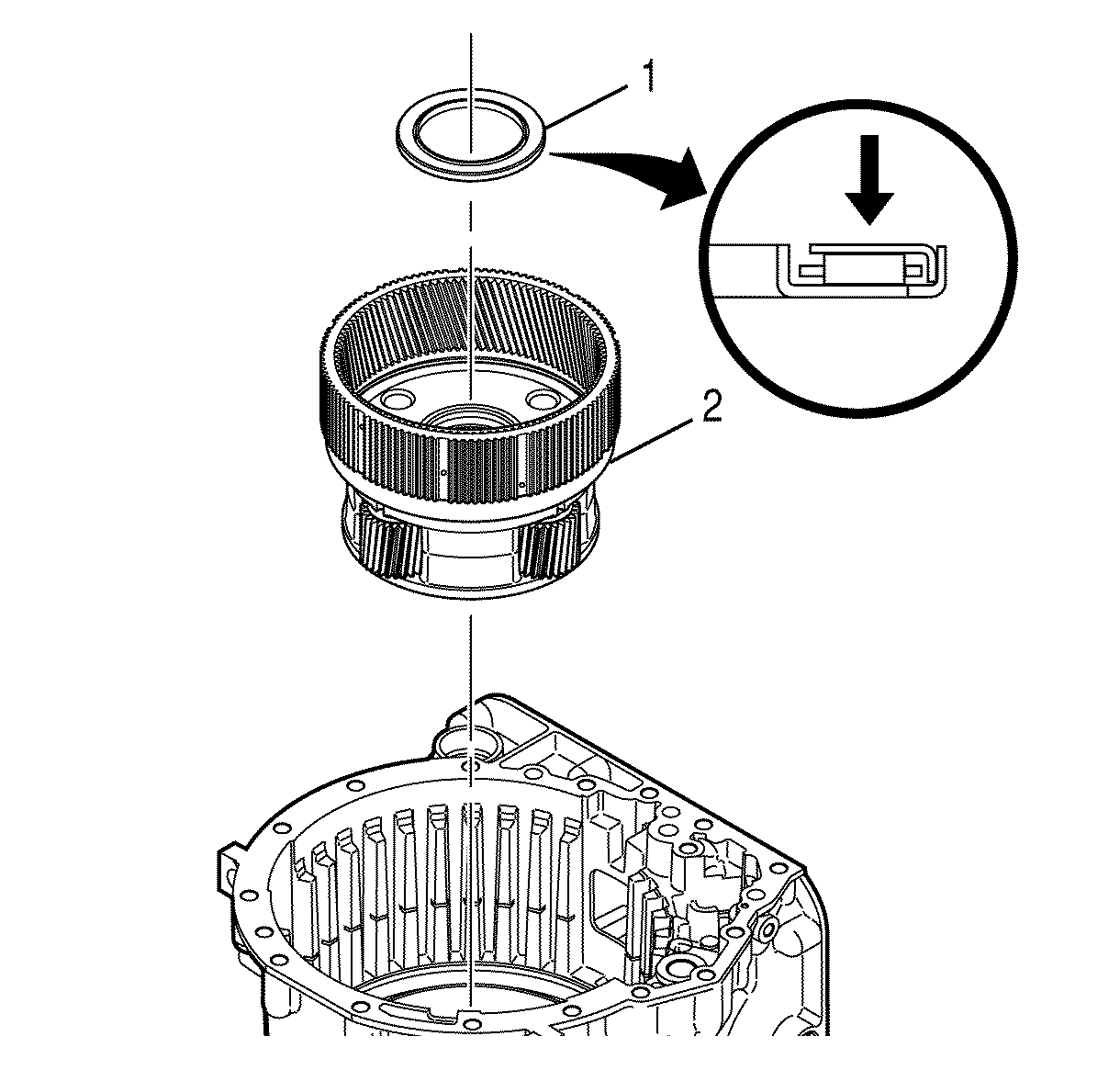
Notice: Installing the thrust bearing incorrectly may cause permanent damage to the transmission.
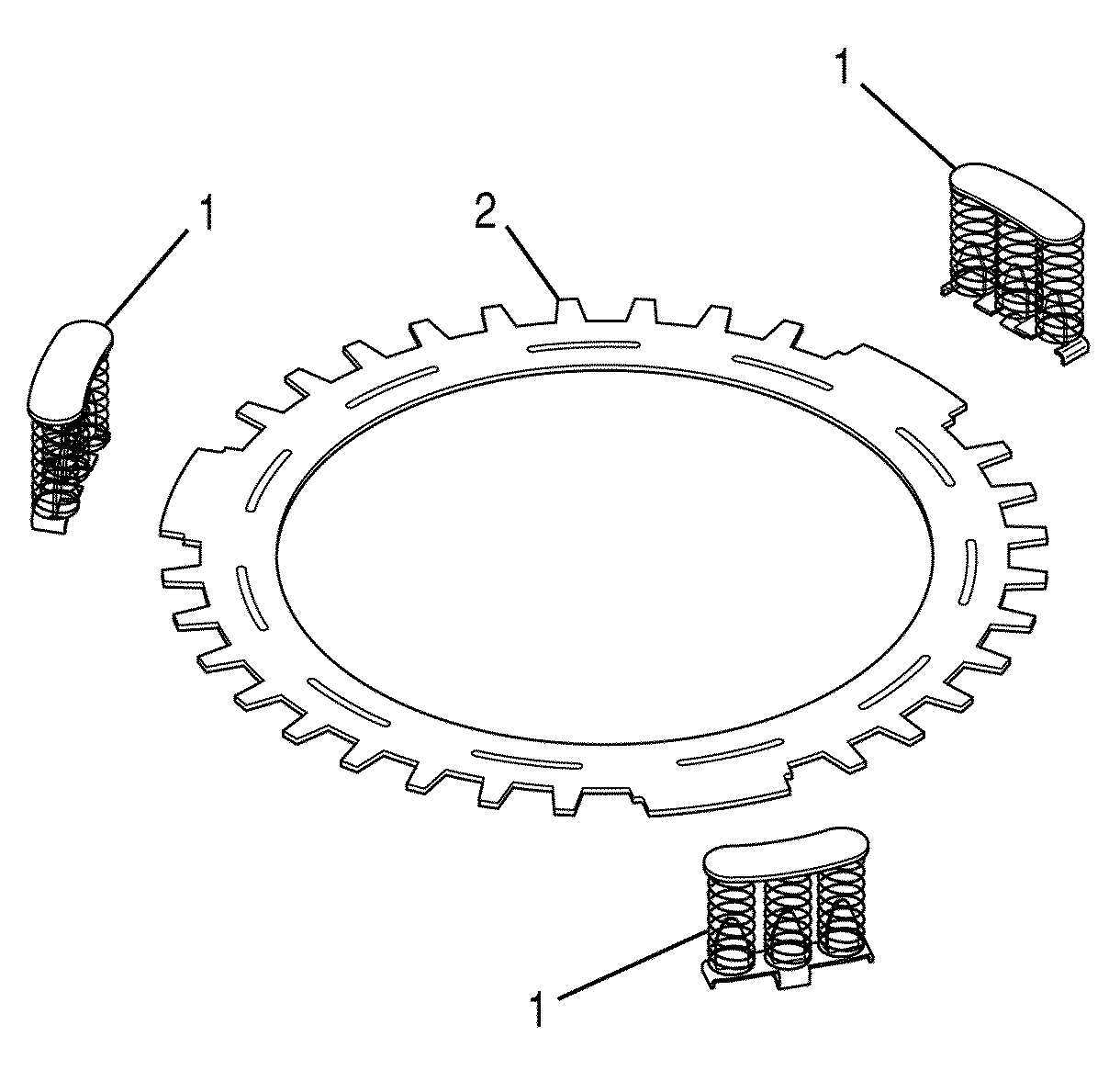
Important: The spring assemblies can be reused. If necessary, squeeze the spring assembly tabs with pliers to make sure the spring assemblies snap onto the 2nd clutch spring plate.
Notice: Refer to 3-5 Reverse Clutch Backing Plate Rivet Damage Notice in the Preface section.
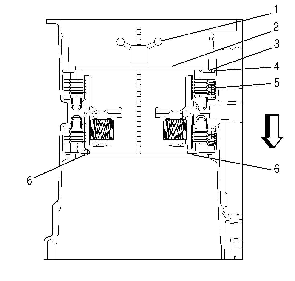
Important: The outer 2nd clutch retaining ring is thinner and larger in circumference compared to the inner low and reverse clutch retaining ring.
Important: Position the 2nd clutch and the low and reverse clutch retaining ring gaps 180 degrees apart.
Important: DO NOT damage the input carrier bushing when removing J 24204-2 from the transmission case. The threaded rod of J 24204-2 must pass through but not touch the bushing.
