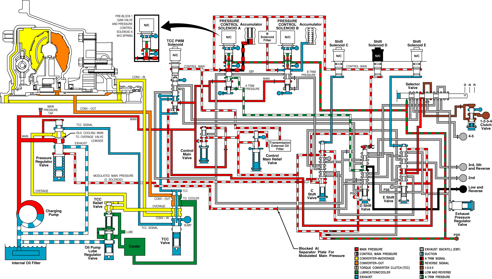
When the selector lever is moved from Neutral (N) to Drive (D), the transmission shifts from Neutral (N) to first range operation. Shift solenoids C, D, and E remain energized. Pressure control solenoid A and the torque converter clutch pulse width modulated (TCC PWM) solenoid remain de-energized
Shift valves C, D and E stay in the down position. With normally closed pressure control solenoid A de-energized, trim valve A continues to supply full trim pressure through shift valve D to the low and reverse clutch, keeping the clutch applied. During the shift, pressure control solenoid B energizes, blocking the exhaust of the B trim signal pressure, causing the pressure to rise. The B trim signal pressure pushes the B trim valve down, opening the B trim pressure port to main pressure. The B trim pressure is directed through shift valve C, shift valve E and the manual valve to the 1-2-3-4 clutch, applying the 1-2-3-4 clutch. The transmission control module (TCM) provides current to the pressure control solenoid B, which controls the rate of pressure buildup of the 1-2-3-4 clutch, assuring a smooth transition to first range. The combination of the 1-2-3-4 clutch and the low and reverse clutch application produces first range operation.
After the shift to first range is complete, shift solenoid E is de-energized followed closely by shift solenoid C, timed to prevent E from becoming "latched" down, allowing both valves to move up. pressure control solenoid B is also de-energized, exhausting B trim signal pressure, allowing the B trim valve to move up which exhausts B trim pressure. In the up position, shift valve E routes main pressure to the manual valve which directs the main pressure to the 1-2-3-4 clutch, keeping the 1-2-3-4 clutch applied. With the 1-2-3-4 clutch and the low and reverse clutch applied, the transmission stays in first range.
Control main pressure exhaust for the D pressure switch is blocked by shift valve D, keeping the switch turned on and providing feedback to the TCM that shift valve D is stroked. With shift valve C in the upward position, the pressure feed to switch C is eliminated and with the pressure exhausted, the pressure switch turns off, providing feedback that shift valve C is in the up position. With shift valve E in the upward position, the control main pressure to the E pressure switch is exhausted and pressure switch E turns off, providing feedback that shift valve E is in the up position.
If electrical power is interrupted with the transmission in first range, shift solenoid D is de-energized. Normally closed pressure control solenoid A continues to block the exhaust of the A trim signal pressure, signal pressure remains control main, which results in maximum A trim pressure being maintained. The A trim pressure continues to be directed to shift valve D, which stays down due to the "latching" effect of pressure on 2 different diameter lands and fluid continues to be directed to the low and reverse clutch, keeping the low and reverse clutch applied. Main pressure continues to be directed through shift valve E and the manual valve to the 1-2-3-4 clutch, keeping the 1-2-3-4 clutch applied. The combination of the 1-2-3-4 clutch and the low and reverse clutch application allows the transmission to stay in first range for limp home capability.
If electrical power is interrupted with the transmission in first range, moving the manual valve to Neutral (N) will cut off main pressure to the 1-2-3-4 clutch and the clutch will be exhausted. The low and reverse clutch remains applied. Because only one clutch is applied, the transmission goes to Neutral (N).
If electrical power is interrupted with the transmission in first range, moving the manual valve to Reverse (R) will cut off main pressure to the 1-2-3-4 clutch, exhausting the 1-2-3-4 clutch. The manual valve directs main pressure through the TCC PWM solenoid valve to the bottom of shift valve D, stroking the valve up and opening the path for main pressure to feed the low and reverse clutch, keeping the clutch applied. A trim pressure is then directed to the 3rd, 5th, and reverse clutch, applying the clutch. The combination of the 3rd, 5th, and reverse clutch and the low and reverse clutch application produces Reverse (R) range operation, for limp home capability.
Important: If the selector is put back in forward after Reverse (R) has been attained, the manual valve will direct fluid to the 1-2-3-4 clutch and shift valve D will stay up, directing fluid to the 3rd, 5th, and reverse clutch, resulting in third range operation.
If electrical power is interrupted with the transmission in first range, resulting in only first, Neutral (N) and Reverse (R) operation, the engine may be shut down and restarted to attain Neutral (N), third, and Reverse (R) operation .
First Range Hydraulic Schematic

