Product Safety - Steering Knuckle Interference

| Subject: | 03044A -- Steering Knuckle Interference |
| Models: | 2003 Chevrolet Astro |
| 2003 GMC Safari |
| Rear-Wheel Drive |
This bulletin is being revised to include U.S. and Export vehicles. The original bulletin was for Canadian vehicles only. The service procedure has also been revised.
Condition
General Motors has decided that a defect which relates to motor vehicle safety exists in certain 2003 model year Chevrolet Astro and GMC Safari rear-wheel drive vans. Some of these vehicles have an interference condition between the lower ball joint rubber boots and the steering knuckles that may cut the boots that are intended to seal the ball joints. If the lower ball joint(s) were cut, contamination from the road (salt, dirt, water, etc.) could enter the ball socket area of the ball joint, resulting in accelerated ball joint wear. Once the socket is worn to a size nearly the diameter of the ball, the ball stud can separate from the socket. If the lower ball joint separated while the vehicle was moving, the affected corner of the vehicle would drop down and the coil spring would push the control arm down into contact with the ground, causing the vehicle to slow down. The affected wheel assembly would turn outward, also slowing the vehicle. Although the driver would have steering control of the unaffected wheel, maintaining directional control of the vehicle could become difficult and a crash could occur.
Correction
Dealers are to modify the steering knuckles and replace the lower ball joints.
Vehicles Involved
Involved are certain 2003 model year Chevrolet Astro and GMC Safari vehicles equipped with rear-wheel drive, and built within these VIN breakpoints:
Year | Division | Model | From | Through |
|---|---|---|---|---|
2003 | Chevrolet | Astro | 3B100002 | 3B151887 |
2003 | GMC | Safari | 3B500002 | 3B517262 |
Important: Dealers should confirm vehicle eligibility through GMVIS (GM Vehicle Inquiry System) before beginning recall repairs. [Not all vehicles within the above breakpoints may be involved.]
For US
For dealers with involved vehicles, a Campaign Initiation Detail Report containing the complete Vehicle Identification Number, customer name and address data has been prepared and will be loaded to the GM DealerWorld, Recall Information website. The customer name and address data furnished will enable dealers to follow up with customers involved in this program.
For Canada & IPC
Computer listings containing the complete Vehicle Identification Number, customer name and address data of involved vehicles have been prepared, and are being furnished to involved dealers. The customer name and address data will enable dealers to follow up with customers involved in this recall. Any dealer not receiving a computer listing with the recall bulletin has no involved vehicles currently assigned.
These dealer listings may contain customer names and addresses obtained from Motor Vehicle Registration Records. The use of such motor vehicle registration data for any other purpose is a violation of law in several states/provinces/countries. Accordingly, you are urged to limit the use of this report to the follow-up necessary to complete this program.
Parts Information
Parts Pre-Ship Information - For US
Important: An initial supply of parts required to complete this program will be pre-shipped to involved dealers of record. This pre-shipment is scheduled to begin the week of March 22, 2004. Pre-shipped parts will be charged to dealer's open parts account.
Parts Pre-Ship Information - For Canada
Important: An initial supply of parts required to complete this program will be pre-shipped to involved dealers of record. This pre-shipment is scheduled to began the week of Feb 9, 2004, and was approximately 20% of each dealer's involved vehicles. Pre-shipped parts were charged to dealer's open parts account.
Additional parts, if required, are to be obtained from General Motors Service Parts Operations (GMSPO). Please refer to your "involved vehicles listing" before ordering parts. Normal orders should be placed on a DRO=Daily Replenishment Order. In an emergency situation, parts should be ordered on a CSO=Customer Special Order.
Part Number | Description | Qty |
|---|---|---|
09766421 | Stud Kit, Frt Lwr Cont Arm Ball | 2 |
Special Tool/Video Tape
During the week of December 29, 2003, and continuing through the week of January 26, 2004, each dealer that stocked or sold a 2003 Astro or Safari was shipped a Knuckle Modification Kit, CH-47576, for use in this recall. This tool kit is being furnished at no charge. Additional tool kits, if required, may be purchased by contacting SPX Kent-Moore at 1-800-GM-TOOLS (1-800-468-6657).
For US
An instructional video titled, "2003 Astro/Safari 2WD Steering Knuckle Modification Video - Recall 03044", is available on the GM Service and Parts Operations website. This video demonstrates the use of the new essential tool CH-47576, Knuckle Modification Kit. Dealers without high speed internet connections may order a CD copy of this repair procedure video at their expense from the GM DealerWorld DWD online store or by calling 1-866-700-0001.
To access the video via high speed internet, follow the instructions below:
For US:
- Go to the SI home page in normal fashion: http://service.gm.com.
- Click on the Service Information tab.
- Go to the bottom of the topic list and locate the link for 2003 Astro/Safari 2WD Steering Knuckle Modification Video - Recall 03044.
- RIGHT CLICK on the link.
- Click on OPEN IN NEW WINDOW. This opens the large-size video viewer. If you LEFT CLICK, the viewer will open at reduced size.
- Once the video has downloaded, click the PLAY arrow to view the video. It runs about 4 minutes. Use the slider to control the volume of the narrative soundtrack. You may rewind the video and view it additional times. When you are finished, click on the X in the upper right to close the video viewer.
Tip
The next step is important.
Tip
On some browsers, it may be necessary to drag the viewer to full size using
the arrow in the lower right corner of the viewer.
For Canada
An instructional video entitled, "2003 Astro/Safari 2WD Steering Knuckle Modification Video - Recall 03044", is also available on GMinfoNet. It is found on the Recall Information page of the Service and Body section. This video demonstrates the use of the new essential tool CH-47576, Knuckle Modification Kit.
Service Procedure
The following information provides instructions for cutting away excess material from both steering knuckles with a new essential tool made especially for this recall. Removal of the material will provide improved clearance for the lower ball joint boot. The procedure also provides information on replacing both lower ball joints. For additional information, refer to the video mentioned above.
| • | J 23742 Ball Joint Separator |
| • | J 9519-E Lower Ball Joint Remover/Installer |
| • | CH-47576 Knuckle Modification Kit |
- Place the ignition switch in the OFF position so that the front wheels can be turned left or right as needed during the procedure.
- Raise the vehicle on a suitable lift and support as necessary.
- Remove both front tire and wheel assemblies.
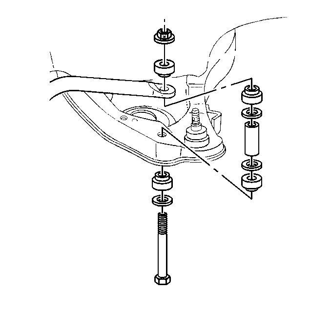
- Remove the two bolts attaching the lower shock absorber to the lower control arm.
- Rotate the end of the shock absorber as necessary and push the shock up through the hole in the lower control arm and into the coil spring.
- Remove the stabilizer link from the lower control arm and from the stabilizer bar.
- Support the lower control arm.
- Remove the cotter pin and nut that attaches the lower ball joint to the knuckle.
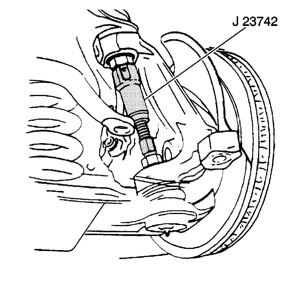
- Using tool J 23742, Ball Joint Separator, separate the lower ball joint from the steering knuckle.
- Remove tool J 23742.
- Carefully lower the lower control arm until the ball joint has cleared the knuckle and the support can be removed.
- With the knuckle still attached to the upper ball joint, carefully swing the lower portion of the knuckle forward. Then for the right side knuckle, rotate the knuckle as if making a slight left turn. For the left side knuckle, rotate the knuckle as if making a right turn.
- Using a shop towel, clean the top and bottom side of the knuckle where the lower ball joint is attached.
- Inspect for the presence of the extra casting material at the two locations (1) shown in the above illustration.
- Using a grinding type tool, carefully remove approximately 10 mm (3/8 in) off of the length of the extra casting material. When completed, the surface where the casting was removed should be flush or even with the horizontal surface.
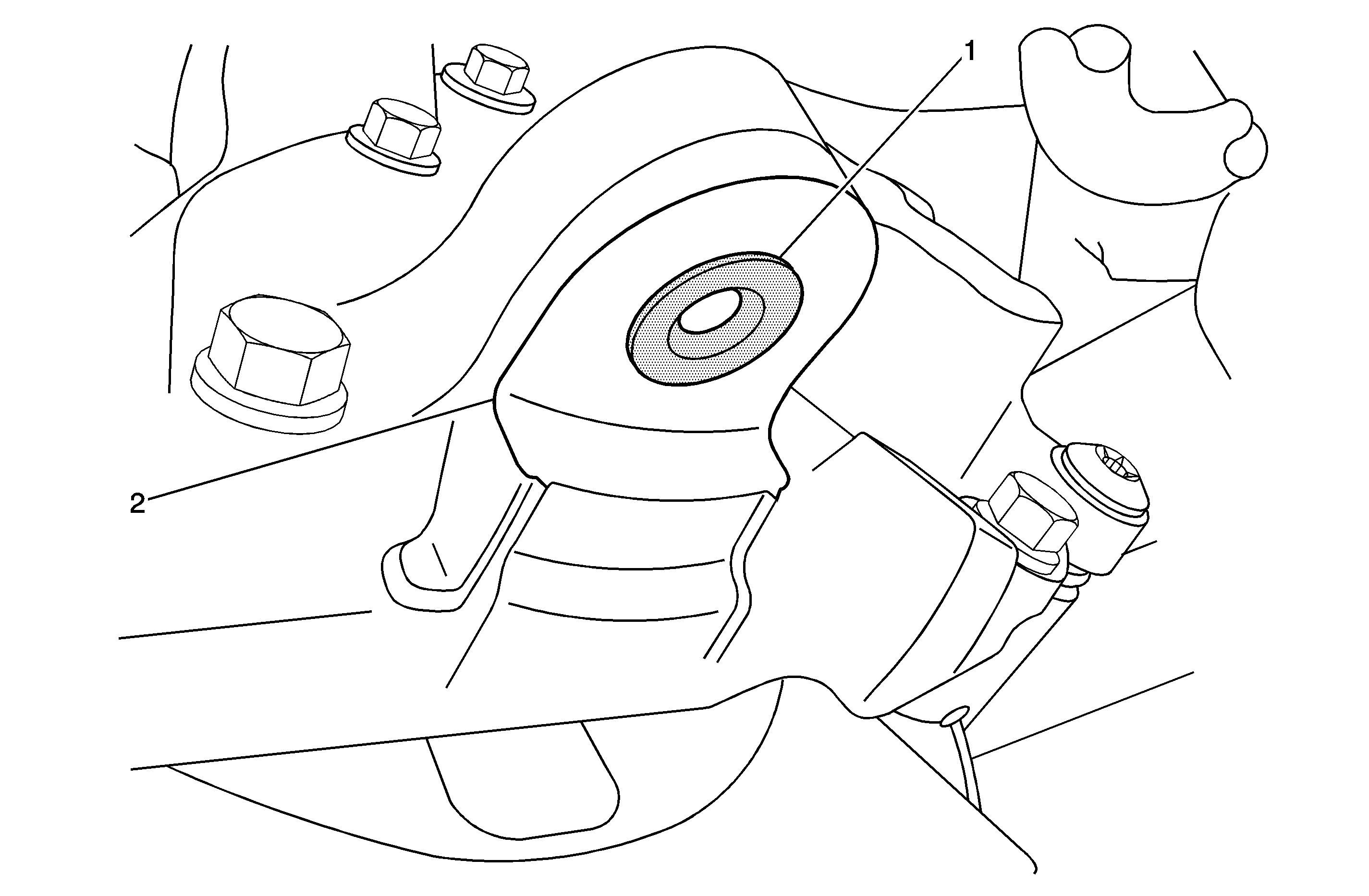
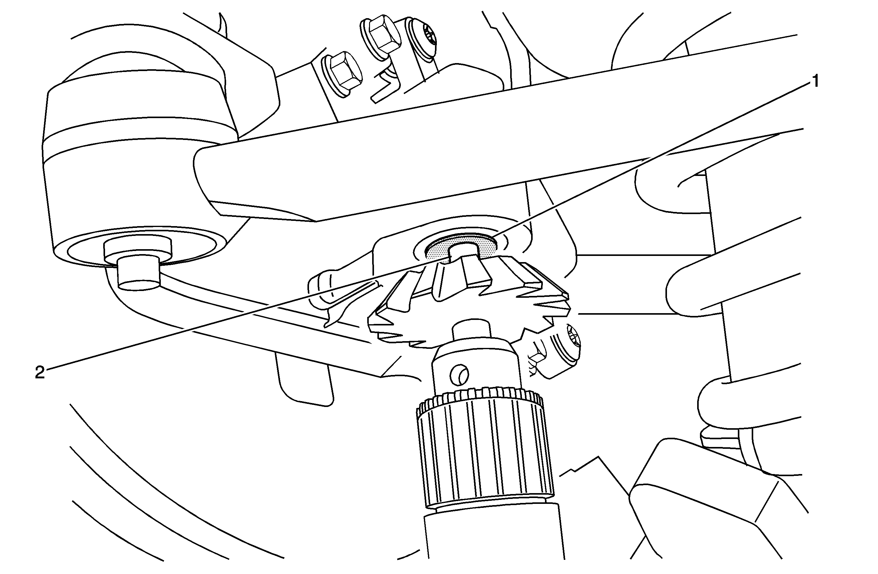
- Install the pilot guide (1) contained in CH-47576, Knuckle Modification Kit, up through the hole in the knuckle (2) as shown. When properly installed, the brass washer included with the pilot guide will be between the pilot guide and the knuckle, and the steel washer (also included) will be between the knuckle and the wing nut.
- Tighten the wing nut securely.
- Place the cutting tool (1) contained in CH-47576, into a 1/2-inch drive electric drill and tighten securely.
- Apply a light film of engine oil on the pilot shaft of the cutter.
- Place the pilot shaft (2) of the cutting tool up into the hole in the pilot guide (1) attached to the knuckle until the cutter blades are approximately 6 mm (1/4 in) away from the knuckle.
- Start the drill and cutting tool spinning in the forward direction and slowly bring the cutter blades (2) up until contact is made with the knuckle (1). When contact occurs, a few metal shavings (3) will begin to appear.
- Keep moving the cutting tool and drill in an upward direction until the face (2) of the cutter contacts the flat surface (1) on the knuckle. When contact occurs the metal shavings will stop and the electric drill motor will begin to spin more freely.
- Remove the cutter and drill from the pilot guide.
- Inspect the knuckle and verify that there is a small newly cut area in the radius of the knuckle surface (1) like that shown in the illustration above.
- Loosen the wing nut and remove the pilot guide and washer.
- Using a shop towel and compressed air, remove the metal shavings from the knuckle, lower control arm, and surrounding parts.
- Support the lower control arm as necessary.
- Remove the rubber grease boot seal from the lower ball joint in the lower control arm.
- Using tool J 9519-E, Lower Ball Joint Remover/Installer, as shown in the above illustration, press out the original lower ball joint from the lower control arm.
- With the new grease purge opening in the boot seal facing inboard toward the coil spring, insert the new lower ball joint into the hole in the lower control arm. The grease purge opening is a small opening in a small hole in the top of the boot at the ball stud.
- Using tool J 9519-E as shown, press the new lower ball joint into the lower control arm. Continue pressing until the ball joint bottoms in the control arm.
- Remove the tool and reposition the knuckle back to its original position.
- While raising the lower control arm, align the ball joint stud and install it in the knuckle.
- Install the new retaining nut included with the new ball joint.
- Install the new cotter pin. If necessary, tighten the nut slightly in order to insert the cotter pin through the lower ball joint stud. Bend the cotter pin ends against the flats of the nut.
- Using a grease gun, grease the new lower ball joint until a small amount of grease comes out of the purge opening in the boot seal.
- Assemble and install the stabilizer link to the lower control arm and stabilizer shaft.
- Pull the bottom of the shock absorber down through the opening in the lower control arm and align it. Install the bolts.
- Install the tire and wheel assembly.
- Repeat Steps 4-37 on the opposite side knuckle and lower ball joint.
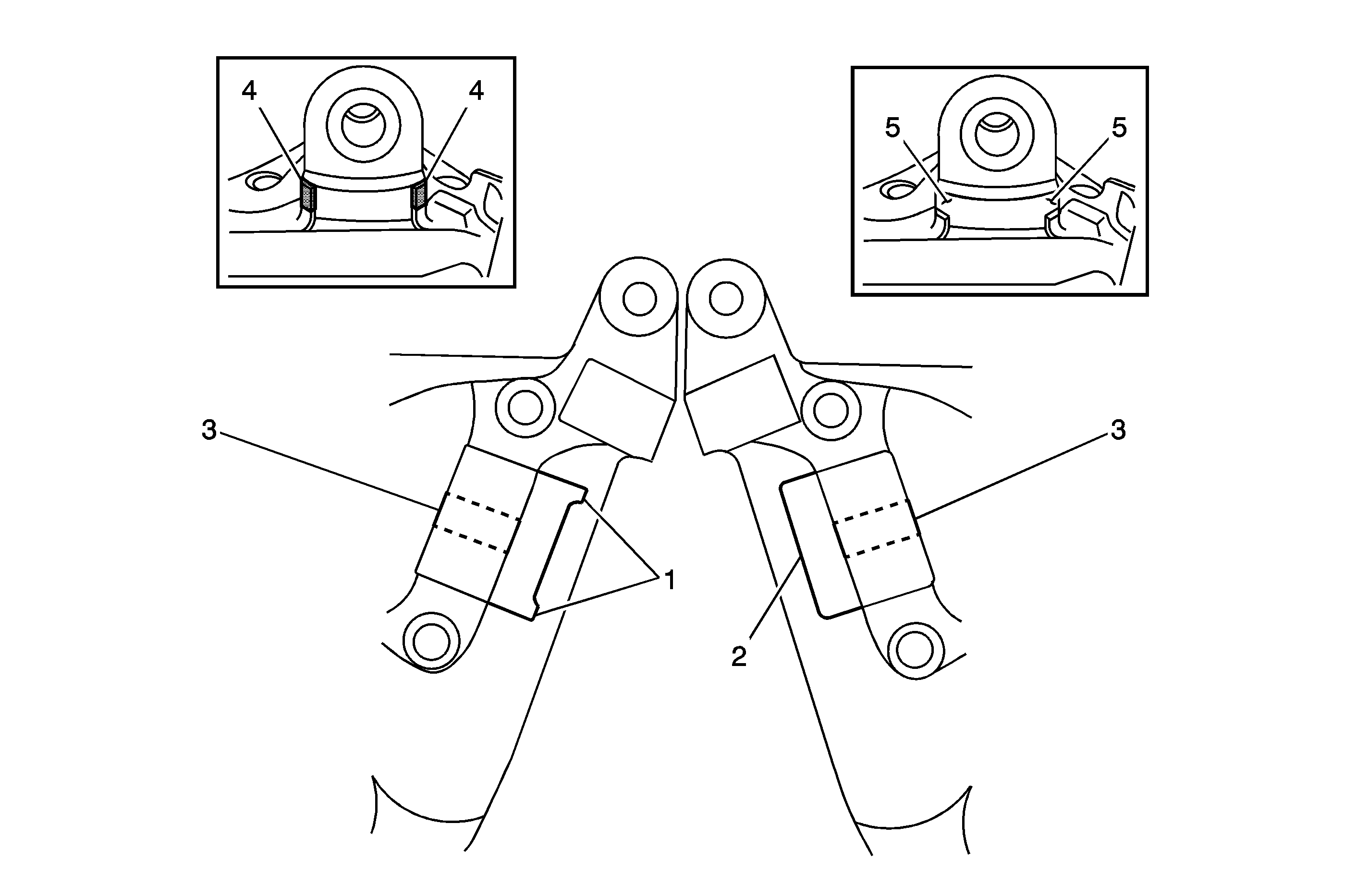
Notice: The inspection, and grinding if necessary, described in the next steps must be performed before using the cutter tool. Failure to perform the inspection, and grinding if necessary, will result in damage to the blades on the cutter tool.
Important: Due to variation in the casting molds used during manufacturing, some knuckles were made with additional or extra casting material (1) along the horizontal surface directly outboard of the hole (3) where the lower ball joint stud attaches. This additional casting material will vary in size and thickness and must be removed BEFORE using the cutter tool. In the above illustration, the knuckle on the right is an example of a knuckle manufactured WITHOUT the extra casing material. The horizontal surface (2) is smooth from side to side. The one on the left shows a knuckle WITH the extra material (1) that must be removed. The illustration in the small box in the upper left corner of the illustration shows how much of the extra casting material (4) must be removed in the next steps. The illustration in the small box in the upper right corner shows how the knuckle should look after the extra material (5) has been remove.
| • | If no extra casting material is found, proceed to Step 16. Do not perform Step 15. |
| • | If extra casting material is found at either location on a knuckle, proceed to Step 15 and remove the casting material. |
Important: It is only necessary to remove some of the extra casting material in the next step. The section to be removed should be approximately 10 mm (3/8 in) long and the width of the extra material. Remove only as much material as instructed and shown in the above illustration. The shaded area in the illustration above represents the amount of material to remove at each location.
Important: To better understand the operation of the knuckle modification tool and pilot guide, refer to the video described in the Special Tool/Video Tape section of this bulletin.
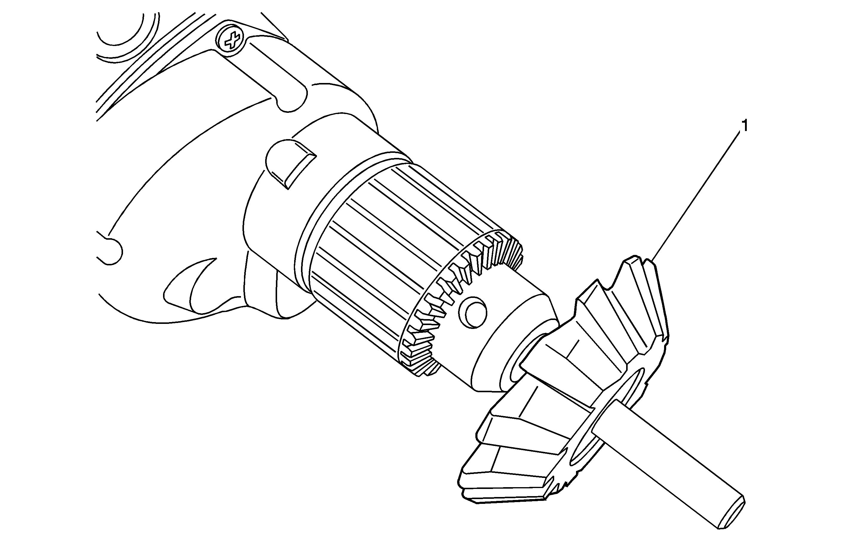
Important: For best cutter performance, it is recommended that a 5 amp or larger electric, 1/2 inch drive, variable speed (200-500 RPM range) drill be used. Using an electric drill with less than 5 amps will cause the cutting time of each knuckle to be significantly longer.
Caution: Safety glasses and gloves are required when performing the cutting operation.
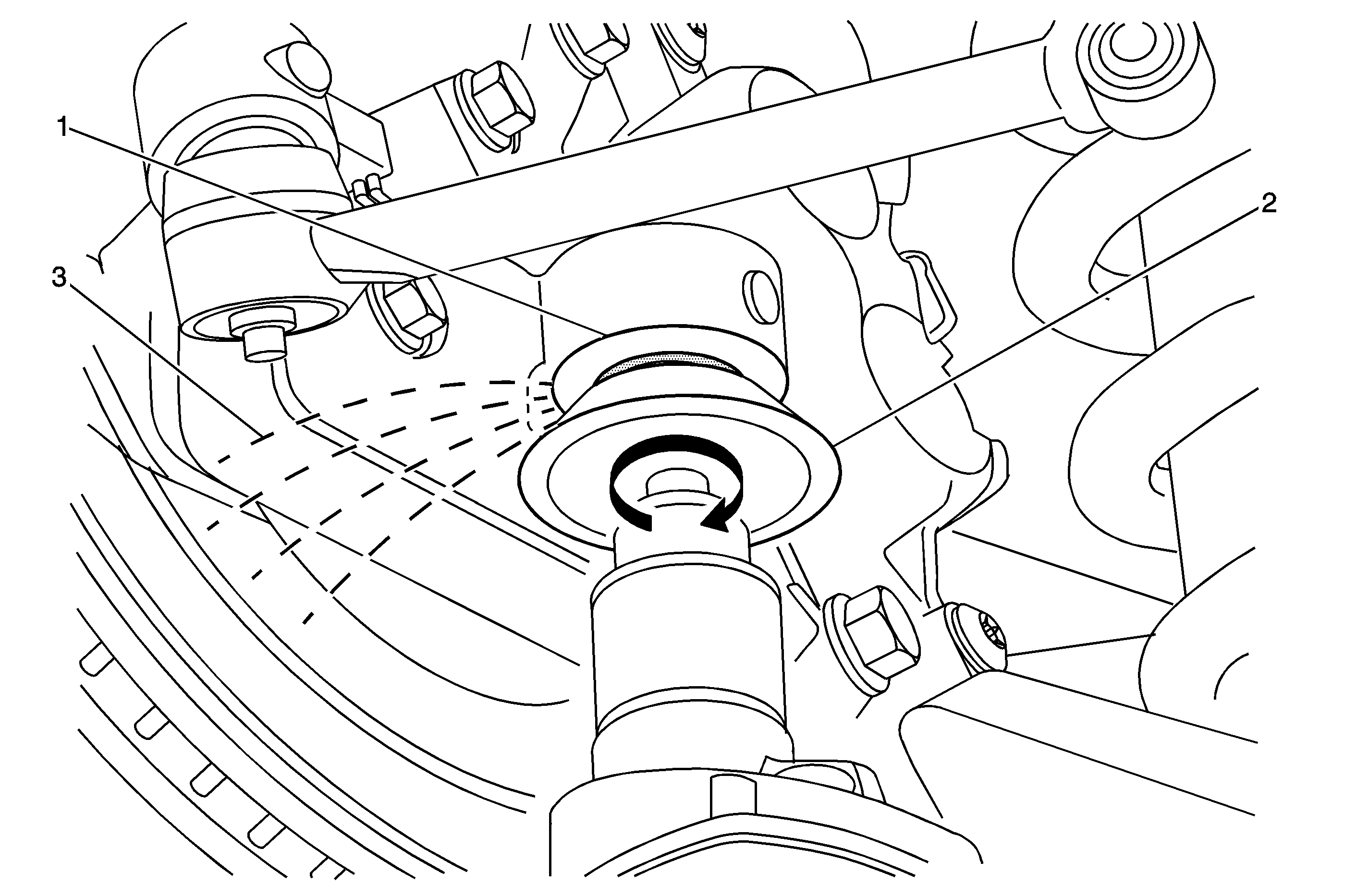
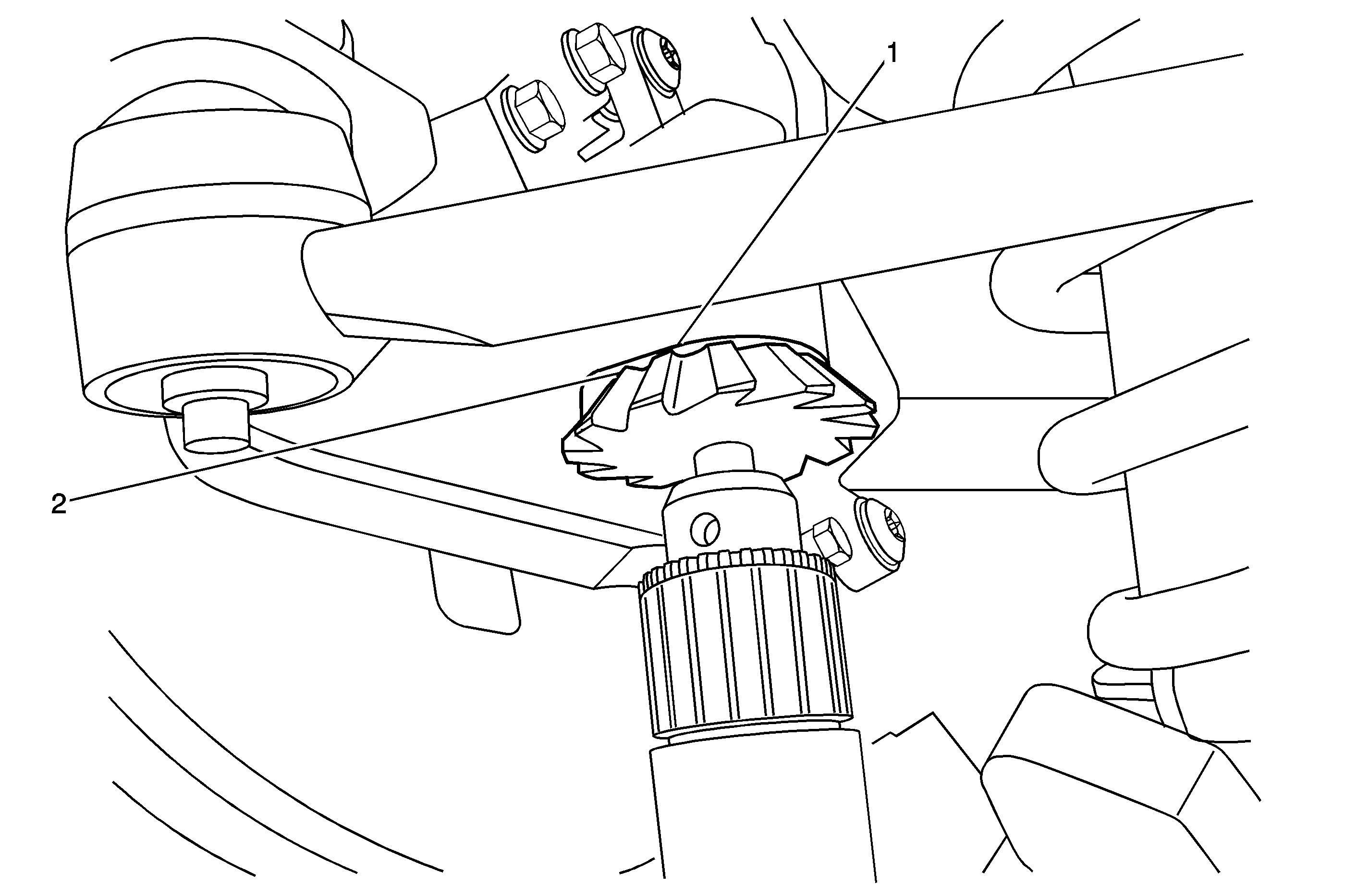
Notice: The cutter and drill will vibrate when in use in the next step. It should take less than 2 minutes to completely cut one knuckle. Do not attempt to speed up the process by using a faster drill or by applying excessive force. Doing so will cause excessive heat buildup in the cutter and may cause premature wear-out.
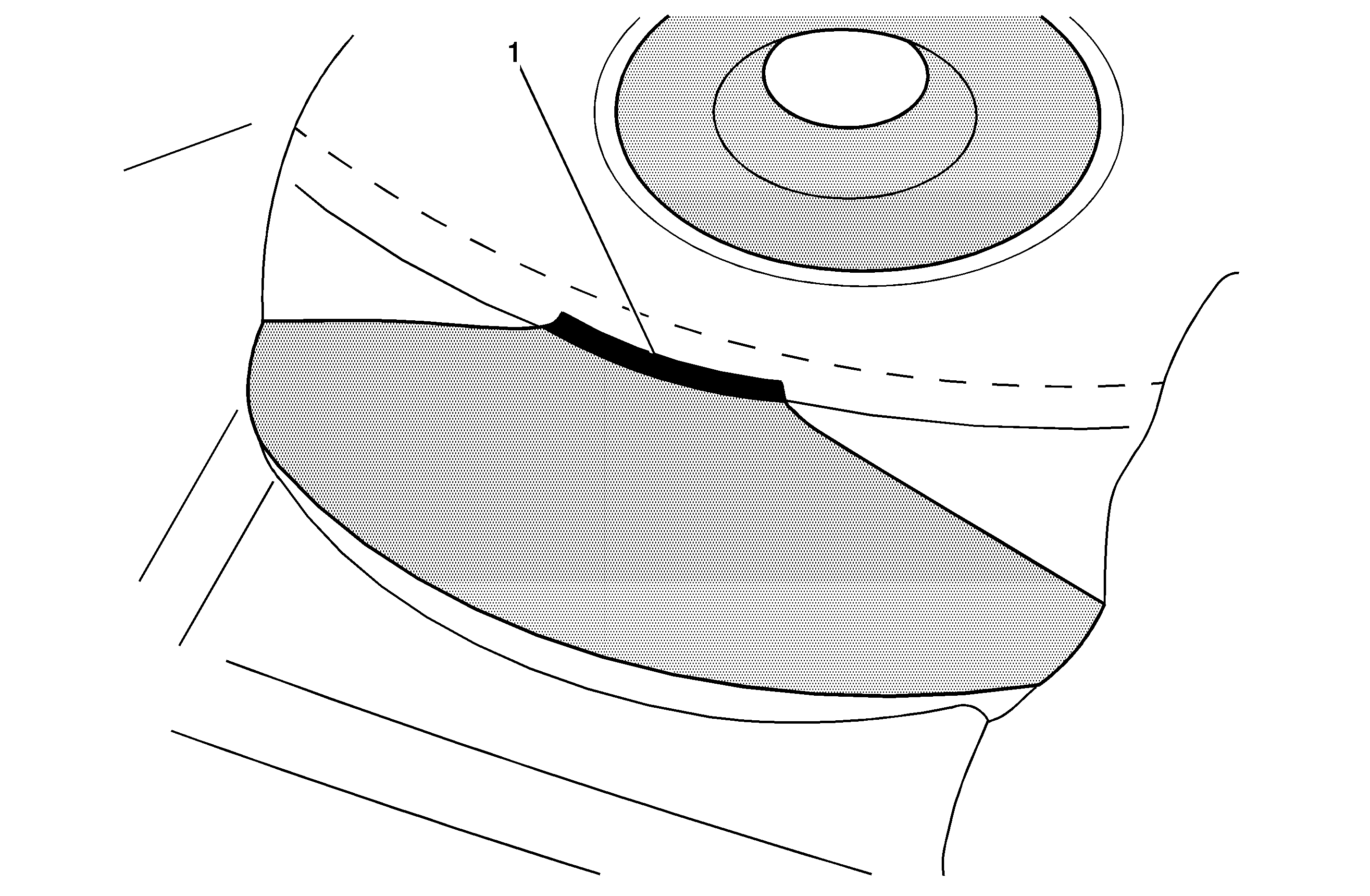
| • | If the small area IS present, then the knuckle was cut "completely". Proceed to the next step. |
| • | If the small area is NOT present, then the cutting operation was NOT fully completed. Reinsert the cutting tool in the pilot and continue cutting the knuckle until the face of the cutting tool contacts the flat surface on the knuckle and the small area is formed. |
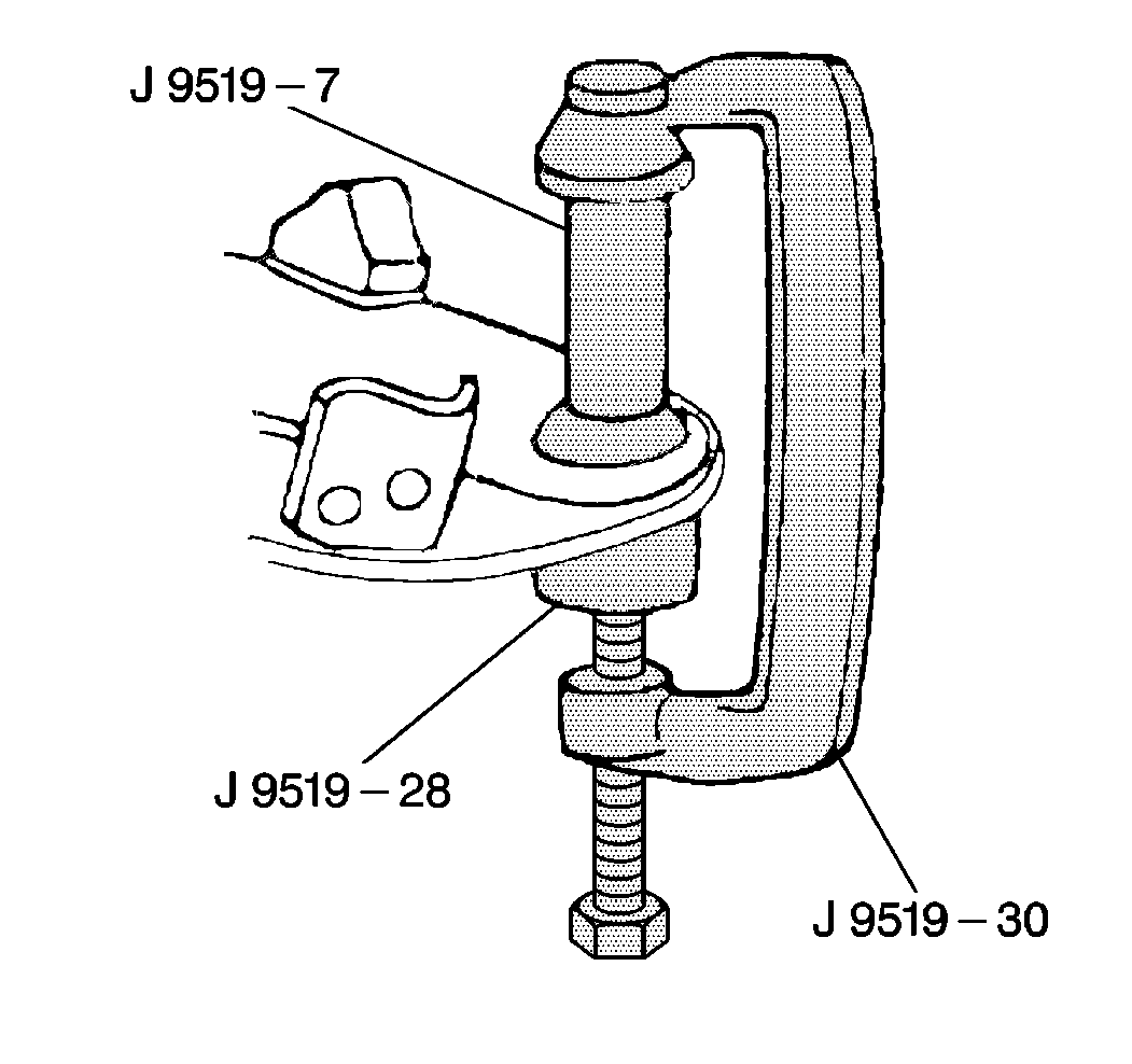
Important: DO NOT remove the grease boot seal from the new lower ball joint.
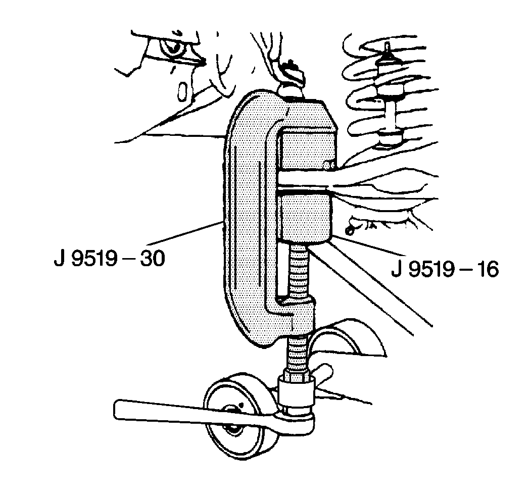
Tighten
Tighten the nut to 125 N·m (92 lb ft).
Tighten
Tighten to 17 N·m (13 lb ft).
Tighten
Tighten the bolts to 25 N·m (18 lb ft).
Tighten
Tighten the nuts to 190 N·m (140 lb ft).
Courtesy Transportation
The General Motors Courtesy Transportation program is intended to minimize customer inconvenience when a vehicle requires a repair that is covered by the New Vehicle Limited Warranty. The availability of courtesy transportation to customers whose vehicles are within the warranty coverage period and involved in a product recall is very important in maintaining customer satisfaction. Dealers are to ensure that these customers understand that shuttle service or some other form of courtesy transportation is available and will be provided at no charge. Dealers should refer to the General Motors Service Policies and Procedures Manual for Courtesy Transportation guidelines.
Claim Information
Submit a Product Recall Claim with the information indicated below:
Repair Performed | Part Count | Part No. | Parts Allow | CC-FC | Labor Op | Labor Hours* |
|---|---|---|---|---|---|---|
Modify Both Steering Knuckles and Replace Lower Ball Joints (Inc. Grinding, if req'd) | 2 | -- | ** | MA-96 | V1055 | 1.6 |
Courtesy Transportation | N/A | N/A | N/A | MA-96 | *** | N/A |
* -- For Program Administrative Allowance, add 0.1 hours to the "Labor Hours". ** -- The "Parts Allowance" should be the sum total of the current GMSPO Dealer net price plus applicable Mark-Up or Landed Cost Mark-Up (for IPC) for the stud kits needed to complete the repair. *** -- Submit courtesy transportation using normal labor operations for courtesy transportation as indicated in the GM Service Policies and Procedures Manual. | ||||||
Refer to the General Motors WINS Claims Processing Manual for details on Product Recall Claim Submission.
Customer Notification -- For US and Canada
General Motors will notify customers of this recall on their vehicle (see copy of customer letter included with this bulletin).
Customer Notification -- For IPC
Letters will be sent to known owners of record located within areas covered by the US National Traffic and Motor Vehicle Safety Act. For owners outside these areas, dealers should notify customers using the attached sample letter.
Dealer Recall Responsibility -- For US and IPC (US States, Territories, and Possessions)
The US National Traffic and Motor Vehicle Safety Act provides that each vehicle which is subject to a recall of this type must be adequately repaired within a reasonable time after the customer has tendered it for repair. A failure to repair within sixty days after tender of a vehicle is prima facie evidence of failure to repair within a reasonable time. If the condition is not adequately repaired within a reasonable time, the customer may be entitled to an identical or reasonably equivalent vehicle at no charge or to a refund of the purchase price less a reasonable allowance for depreciation. To avoid having to provide these burdensome remedies, every effort must be made to promptly schedule an appointment with each customer and to repair their vehicle as soon as possible. In the recall notification letters, customers are told how to contact the US National Highway Traffic Safety Administration if the recall is not completed within a reasonable time.
Dealer Recall Responsibility -- All
All unsold new vehicles in dealers' possession and subject to this recall MUST be held and inspected/repaired per the service procedure of this recall bulletin BEFORE customers take possession of these vehicles.
Dealers are to service all vehicles subject to this recall at no charge to customers, regardless of mileage, age of vehicle, or ownership, from this time forward.
Customers who have recently purchased vehicles sold from your vehicle inventory, and for which there is no customer information indicated on the dealer listing, are to be contacted by the dealer. Arrangements are to be made to make the required correction according to the instructions contained in this bulletin. A copy of the customer letter is provided in this bulletin for your use in contacting customers. Recall follow-up cards should not be used for this purpose, since the customer may not as yet have received the notification letter.
In summary, whenever a vehicle subject to this recall enters your vehicle inventory, or is in your dealership for service in the future, please take the steps necessary to be sure the recall correction has been made before selling or releasing the vehicle.
April 2004Dear General Motors Customer:
This notice is sent to you in accordance with the requirements of the National Traffic and Motor Vehicle Safety Act. Federal regulation requires that any vehicle lessor receiving this recall notice must forward a copy of this notice to the lessee within ten days.
Reason For This Recall
General Motors has decided that a defect which relates to motor vehicle safety exists in certain 2003 model year Chevrolet Astro and GMC Safari rear-wheel drive vans. Some of these vehicles have an interference condition between the lower ball joint rubber boots and the steering knuckles that may cut the boots that are intended to seal the ball joints. If the lower ball joint(s) were cut, contamination from the road (salt, dirt, water, etc.) could enter the ball socket area of the ball joint, resulting in accelerated ball joint wear. Once the socket is worn to a size nearly the diameter of the ball, the ball stud can separate from the socket. If the lower ball joint separated while the vehicle was moving, the affected corner of the vehicle would drop down and the coil spring would push the control arm down into contact with the ground, causing the vehicle to slow down. The affected wheel assembly would turn outward, also slowing the vehicle. Although the driver would have steering control of the unaffected wheel, maintaining directional control of the vehicle could become difficult and a crash could occur.
What Will Be Done
To eliminate this interference condition, your GM dealer will modify the steering knuckles on your vehicle and replace the lower ball joints. This service will be performed for you at no charge .
How Long Will The Repair Take?
This service correction will take approximately 1 hour and 40 minutes. However, due to service scheduling requirements, your dealer may need your vehicle for a longer period of time.
Contacting Your Dealer
Please contact your dealer as soon as possible to arrange a service date. Parts are available and instructions for making this correction have been sent to your dealer. Your dealer is best equipped to obtain parts and provide services to correct your vehicle as promptly as possible.
Should your dealer be unable to schedule a service date within a reasonable time, you should contact the appropriate Customer Assistance Center at the number listed below:
Division | Number | Deaf, Hearing Impaired, or Speech Impaired* |
|---|---|---|
Chevrolet | 1-800-630-2438 | 1-800-833-2622 |
GMC | 1-866-996-9463 | 1-800-462-8583 |
Puerto Rico - English | 1-800-496-9992 |
|
Puerto Rico - Español | 1-800-496-9993 |
|
Virgin Islands | 1-800-496-9994 |
|
* Utilizes Telecommunication Devices for the Deaf/Text Telephones (TDD/TTY) | ||
If, after contacting the appropriate customer assistance center, you are still not satisfied that we have done our best to remedy this condition without charge and within a reasonable time, you may wish to write the Administrator, National Highway Traffic Safety Administration, 400 Seventh Street SW, Washington, DC 20590 or call 1-888-327-4236.
Customer Reply Card
The attached customer reply card identifies your vehicle. Presentation of this card to your dealer will assist in making the necessary correction in the shortest possible time. If you no longer own this vehicle, please let us know by completing the attached and mailing it in the postage paid envelope.
Courtesy Transportation
If your vehicle is within the New Vehicle Limited Warranty, your dealer may provide you with shuttle service or some other form of courtesy transportation while your vehicle is at the dealership for this repair. Please refer to your Owner's Manual and your dealer for details on Courtesy Transportation.
We are sorry to cause you this inconvenience; however, we have taken this action in the interest of your safety and continued satisfaction with our products.
General Motors Corporation
Enclosure
