Special Tools
| • | GE-48494 Power Electronics Pressure Test Adapter Kit |
| • | J 24460-01 Cooling System Pressure Tester |
Removal Procedure
- Remove the drive motor generator control module from the vehicle. Refer to Drive Motor Generator Control Module Assembly Replacement.
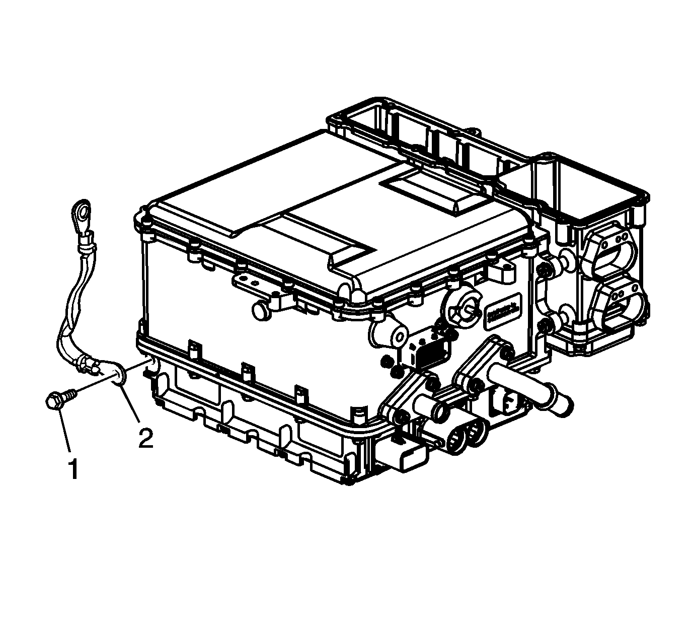
- Remove the APM ground strap bolt (1) and ground strap (2).
- Remove the temporary coolant pipe caps (1).
- Drain the drive motor generator control module assembly of residual coolant by applying 30 psi regulated compressed air to the coolant inlet pipe until no coolant remains.
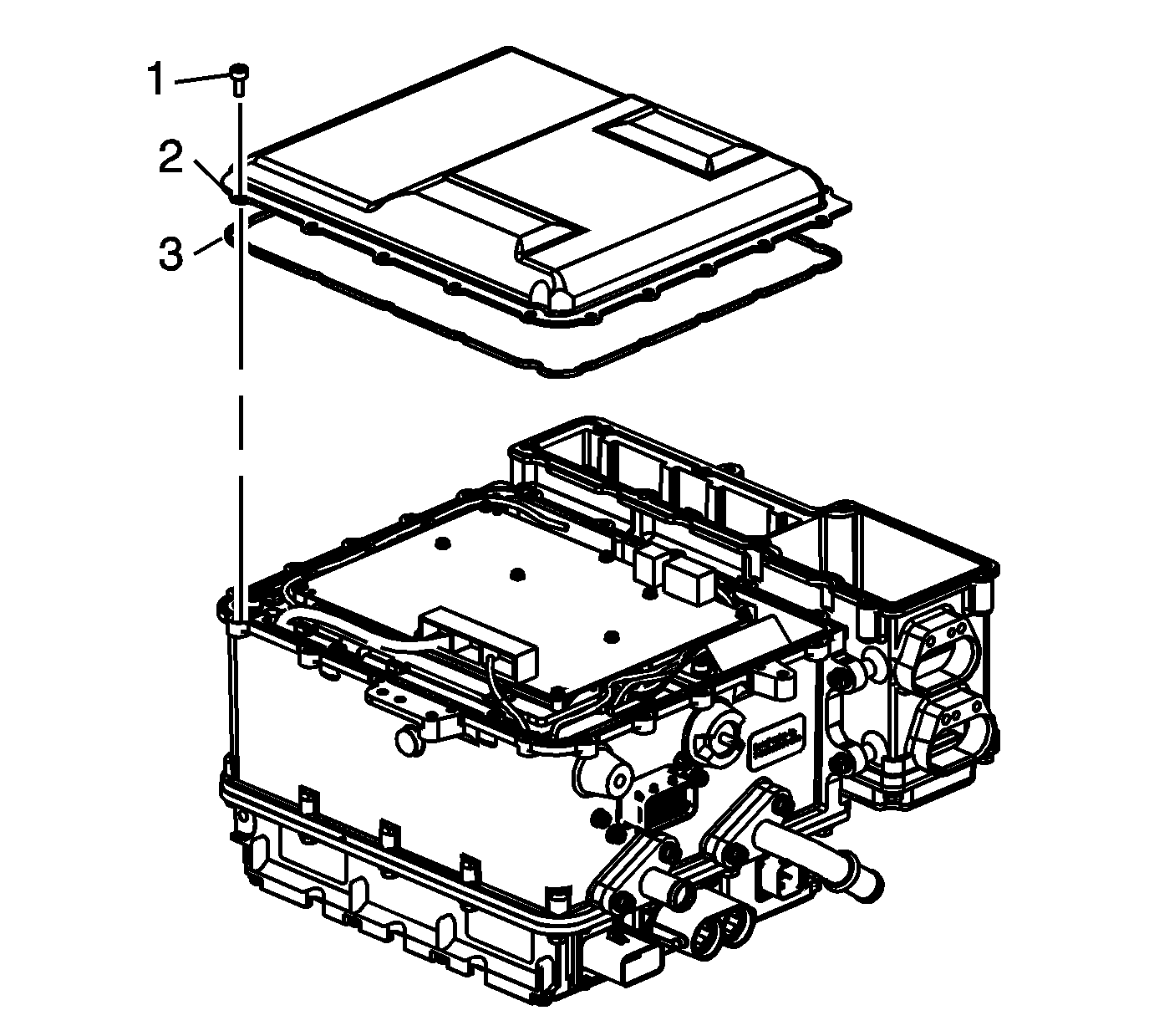
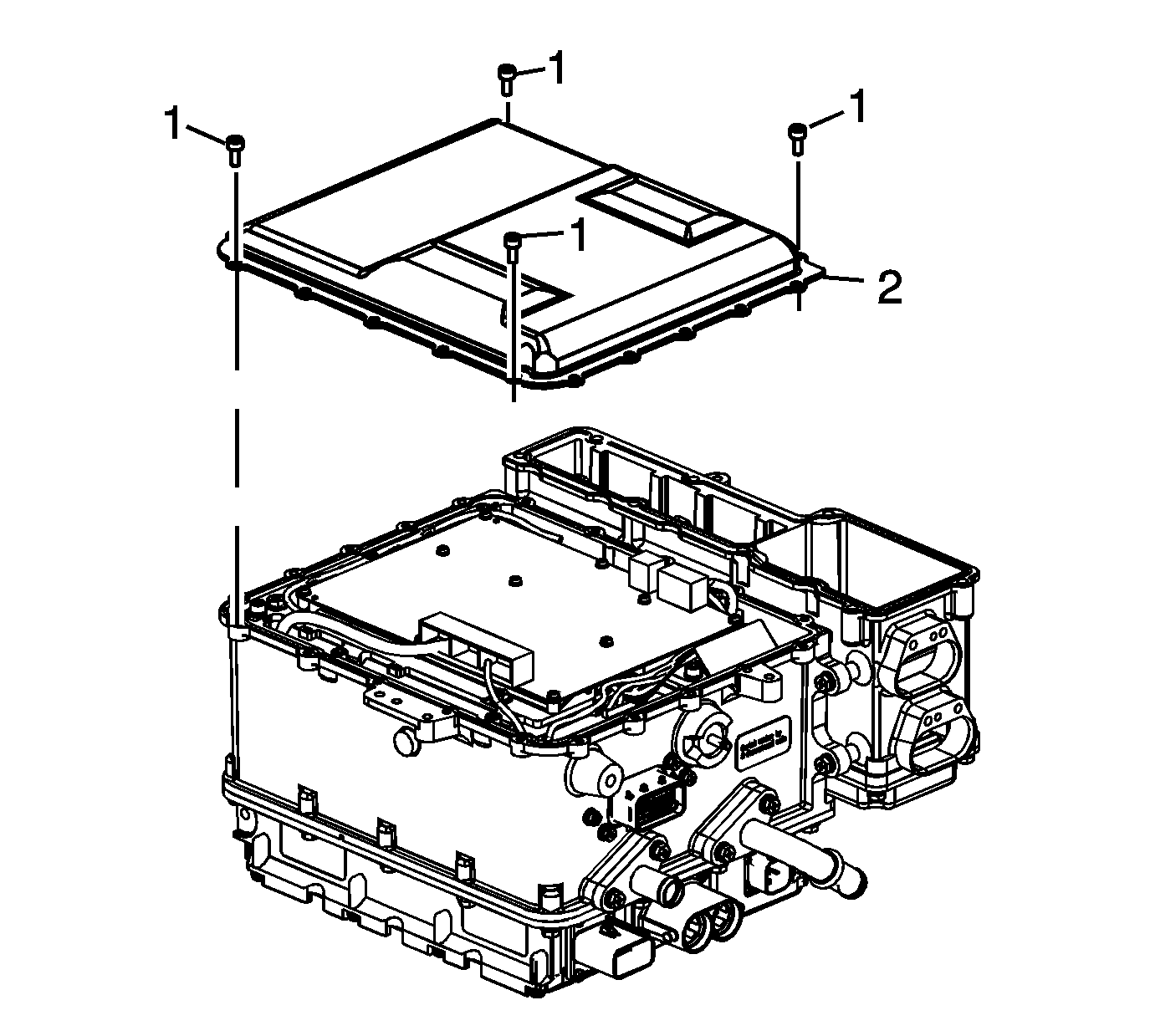
- Remove the drive motor generator power inverter control module (PIM) electronics cover fasteners (1).
- Remove the PIM electronics cover (2). Discard the cover seal (3).
- Remove the HV dc accessory DC power control module (APM) terminal fasteners (1) utilizing a magnetic socket.
- Temporarily install the PIM electronics cover (2) with 4 finger-tightened fasteners (1).
- Rotate the drive motor generator control module assembly onto the PIM electronics cover.
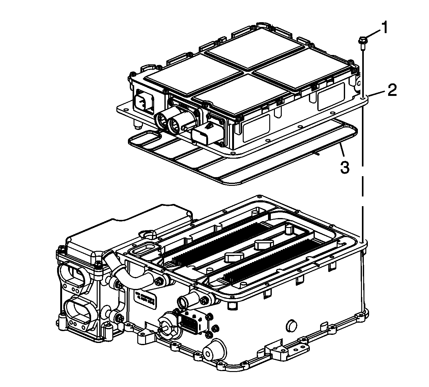
- Remove the APM to PIM mounting fasteners (1).
- Remove the APM (2) and discard the coolant seal (3).
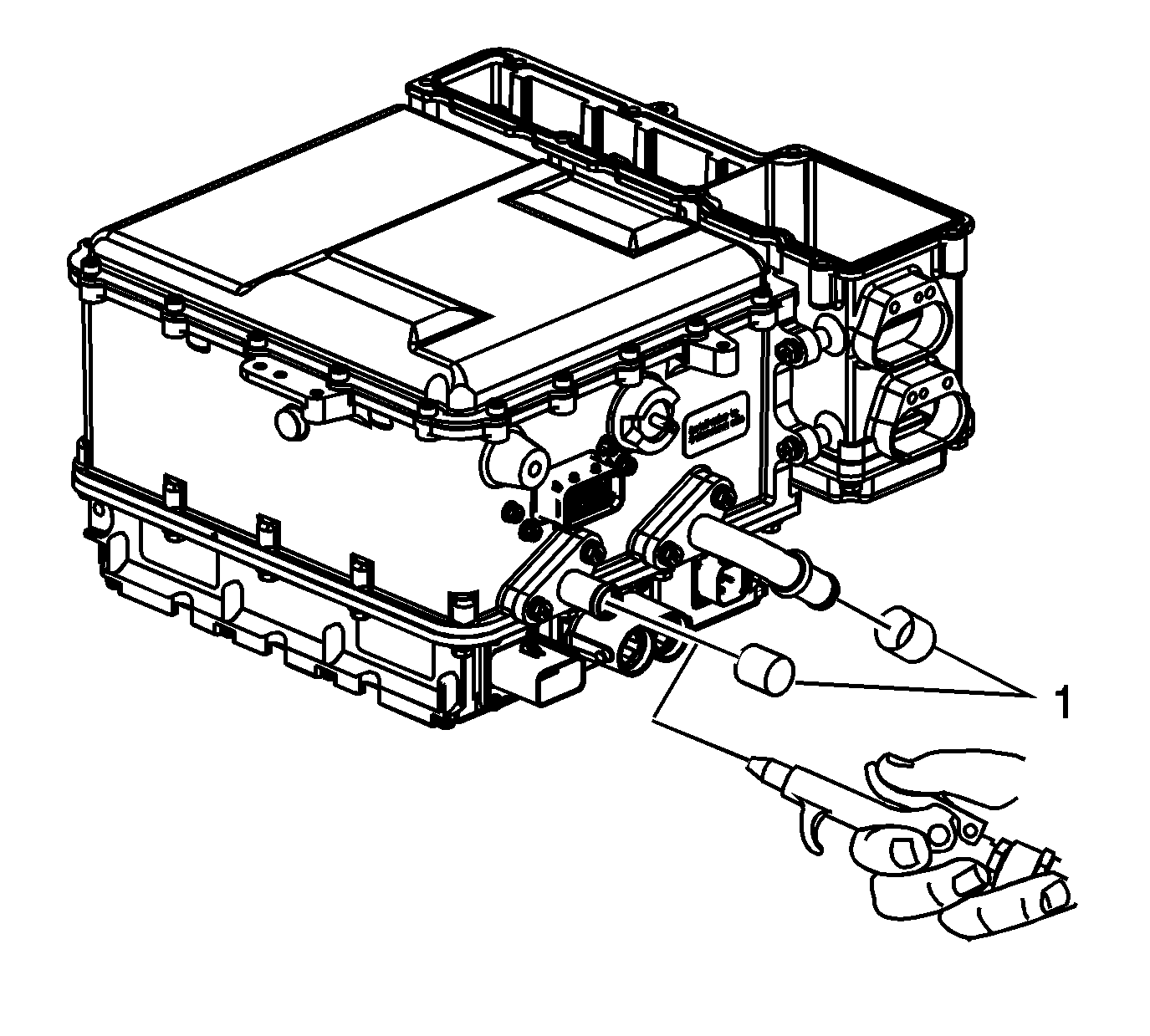
Caution: The module must be drained of all residual coolant prior to disassembly. Failure to properly drain all residual coolant may cause electronic circuit damage to occur during disassembly.
Important: Place a container under the coolant outlet pipe to capture the escaping coolant.
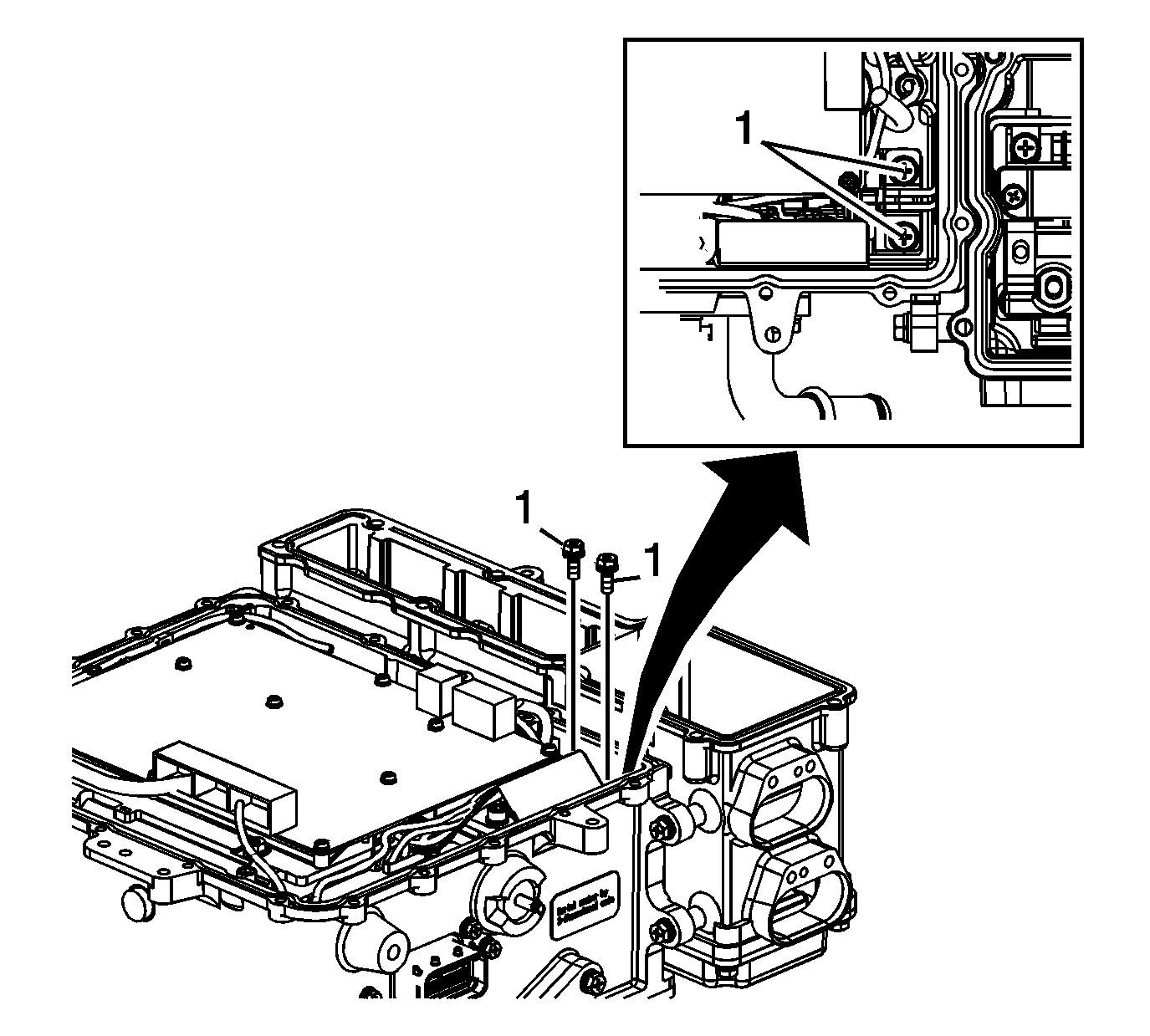
Caution: Always remove and install the High Voltage terminal fasteners with a magnet tipped socket. Never touch the exposed electronic circuit board surface or components. Dropped fasteners or physical contact may result in electronic circuit board damage.
Installation Procedure
- Install new APM coolant seal (3).
- Position the APM (2) onto the PIM ensuring the seals remain in place.
- Install the APM mounting fasteners (1).
- Rotate the drive motor generator control module assembly onto the APM.
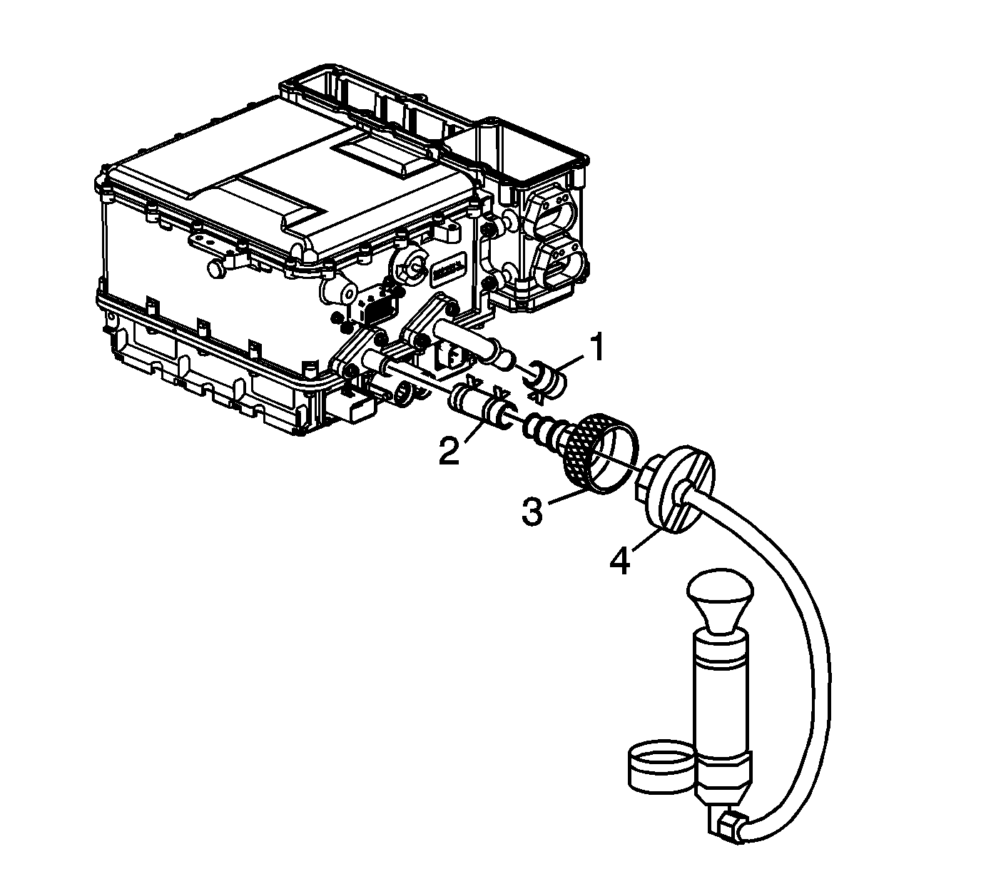
- Clamp the GE-48494 components (2, 3) to a coolant pipe.
- Plug the remaining coolant pipe with the GE-48494 plug and clamp (1).
- Apply the specified pressure with J 24460-01 (4).
- Monitor the pressure tester gauge for 5 minutes and ensure that pressure remains at the specified value.
- Remove all GE-48494 components.
- Remove the PIM cover retaining bolts (1).
- Remove the PIM electronics cover (2).
- Install the HV dc APM terminal fasteners (1) utilizing a magnetic socket.
- Install a new PIM cover seal (3).
- Position the PIM cover (2) onto the PIM ensuring the seal remains in place.
- Install the PIM cover fasteners (1).
- Install the ground strap (2) and bolt (1).

Notice: Refer to Fastener Notice in the Preface section.
Tighten
Tighten the mounting fasteners to 10 N·m (89 lb in).
Pressure
Apply 20 psi (138 kPa) pressure.
| • | If the specified pressure cannot be maintained, disassemble the drive motor generator control module assembly and replace the coolant seals. |
| • | If pressure remains at the specified value, proceed to the next step. |


Caution: Always remove and install the High Voltage terminal fasteners with a magnet tipped socket. Never touch the exposed electronic circuit board surface or components. Dropped fasteners or physical contact may result in electronic circuit board damage.
Tighten
Tighten the terminal fasteners to 9 N·m (80 lb in).

Tighten
Tighten the fasteners to 5 N·m (44 lb in).

Tighten
Tighten the bolt to 22 N·m (16 lb ft).
