Removal Procedure
- Disconnect the negative battery cable. Refer to Battery Negative Cable Disconnection and Connection.
- Disable the SIR system. Refer to SIR Disabling and Enabling.
- Remove all related panels and components.
- Repair as much of the damage as possible to factory specifications. Refer to Dimensions - Body.
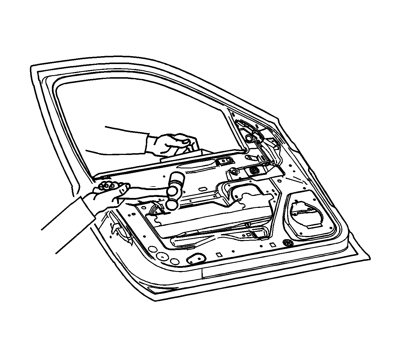
- Remove the door assembly. Refer to Front Side Door Replacement.
- Locate and drill out all factory welds. Note the number and location of welds for installation of the service panel.
- Grind the edges of the door outer panel to separate the outer door panel from the door shell.
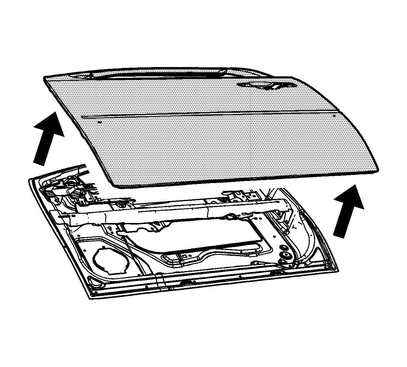
- Remove the outer door panel.
- Remove the sealers and anti-corrosion materials from the repair area, as necessary. Refer to Anti-Corrosion Treatment and Repair.
- Straighten the edges of the door shell.
Warning: Refer to Approved Equipment for Collision Repair Warning in the Preface section.
Note: Before beginning the repair, refer to Metal Panel Bonding for proper adhesive applicator preparations and general information.
Warning: Inspection of the door guard beam for damage must be performed before replacement of the door outer panel. If damage to the door guard beam is found the door must be replaced. Failure to do so may compromise the structural integrity of the vehicle and may cause personal injury if the vehicle is involved in a collision.
Installation Procedure
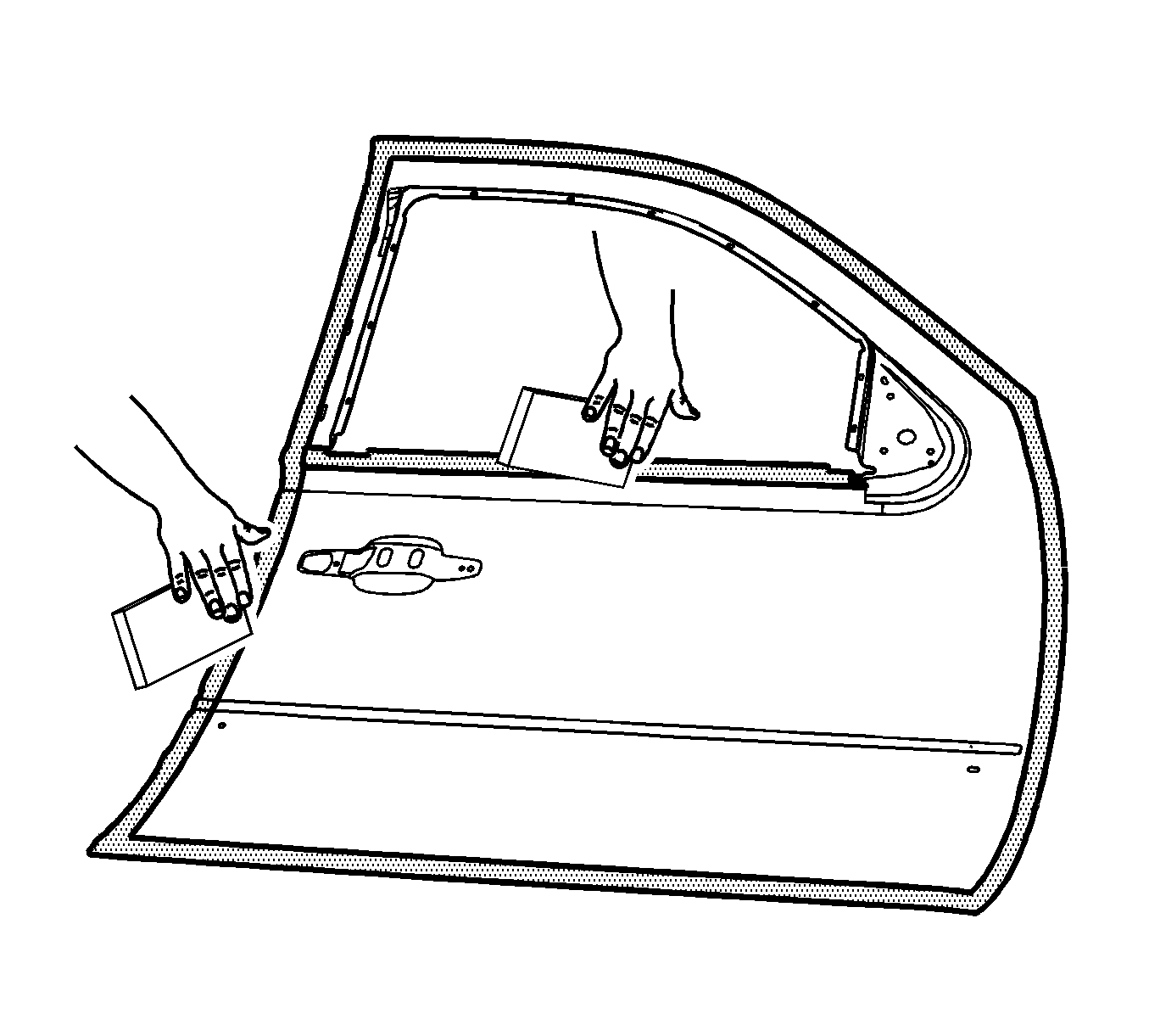
- Using a grinding disk grind the surface of the door shell mating flanges to bare steel.
- Scuff the opposing mating surfaces of the door outer panel to remove the gloss of the E-Coat.
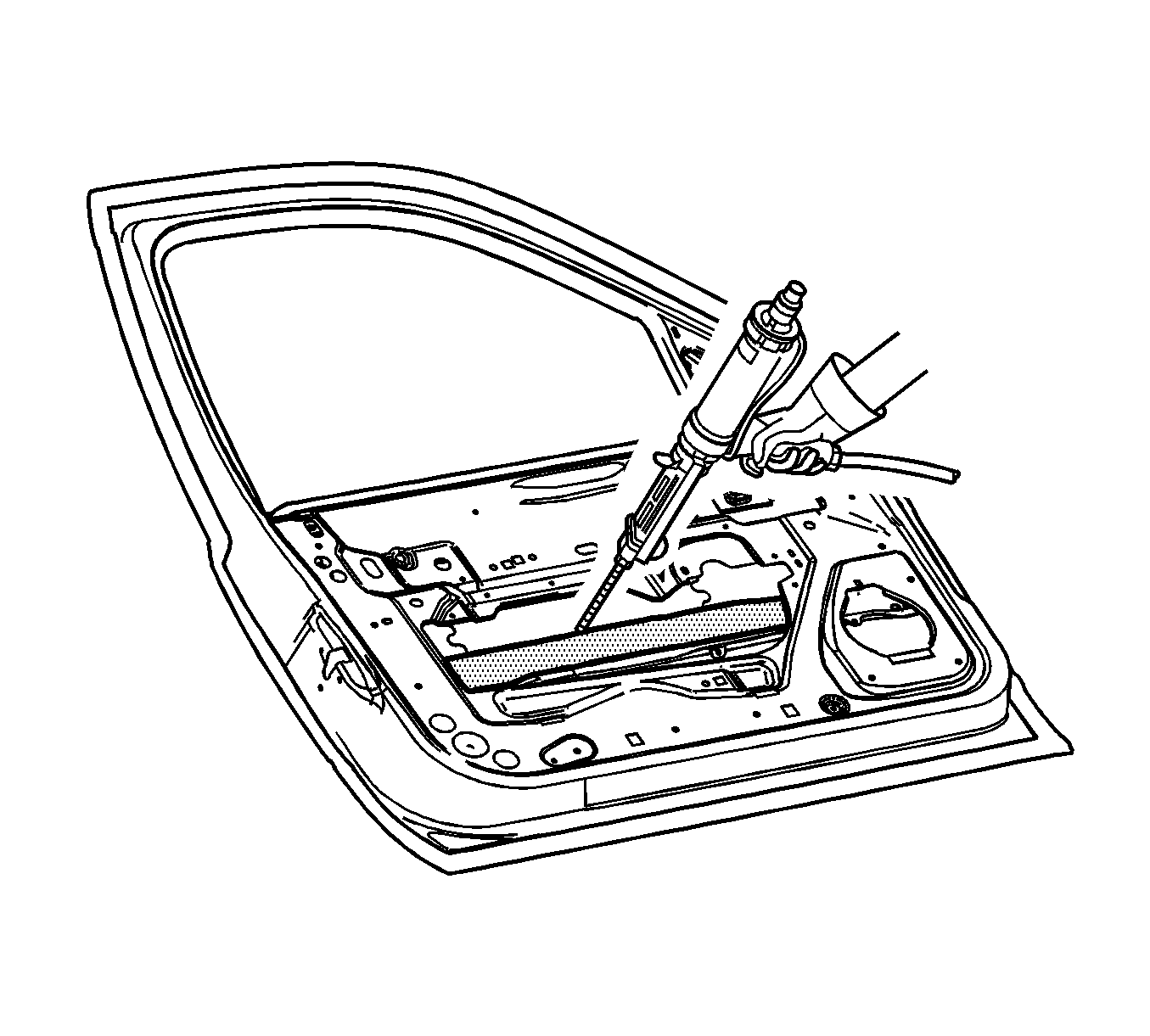
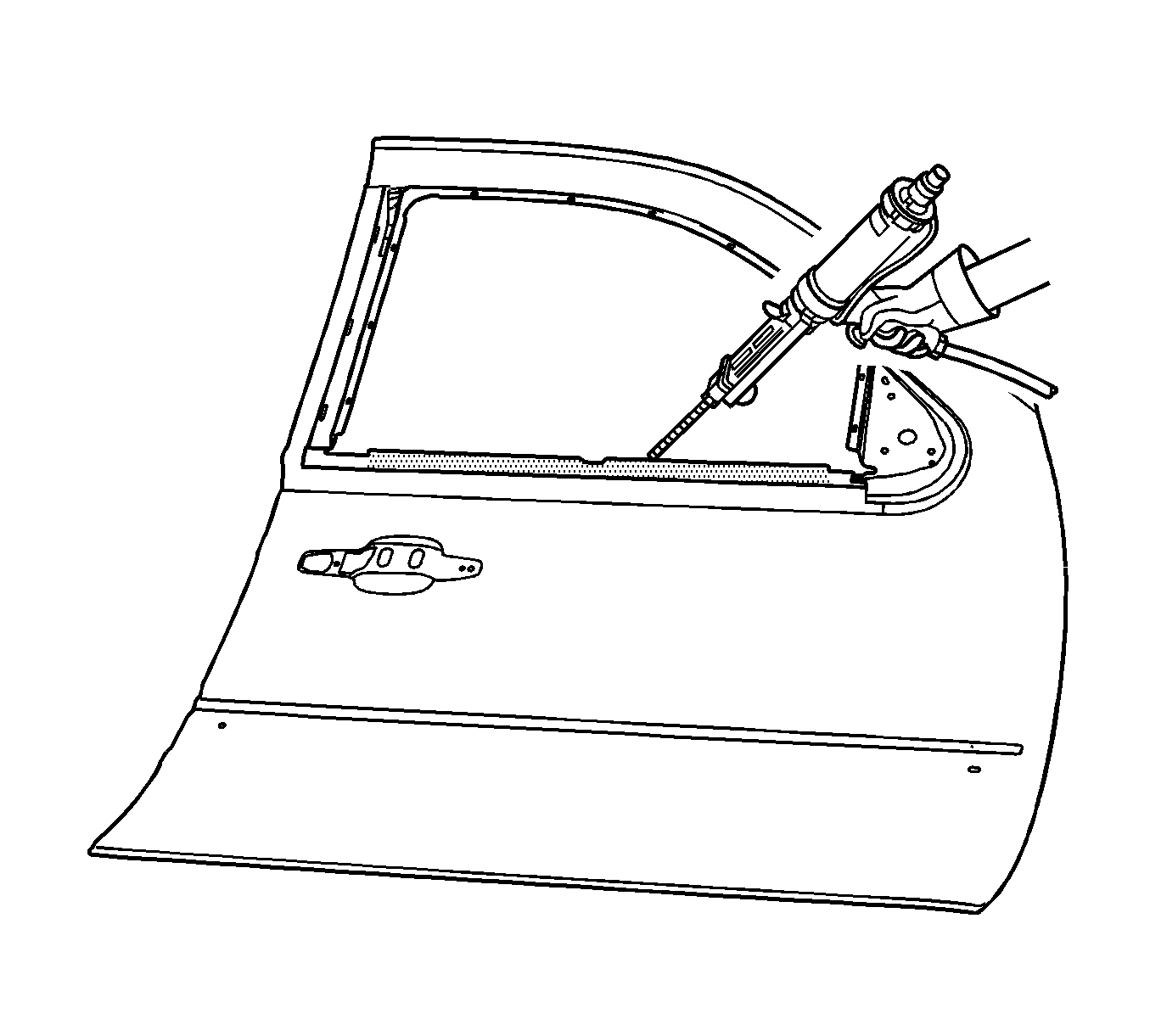
- Drill 8 mm (5/16 in) plug weld holes, as necessary, in the locations noted from the original panel.
- Clean the mating surfaces.
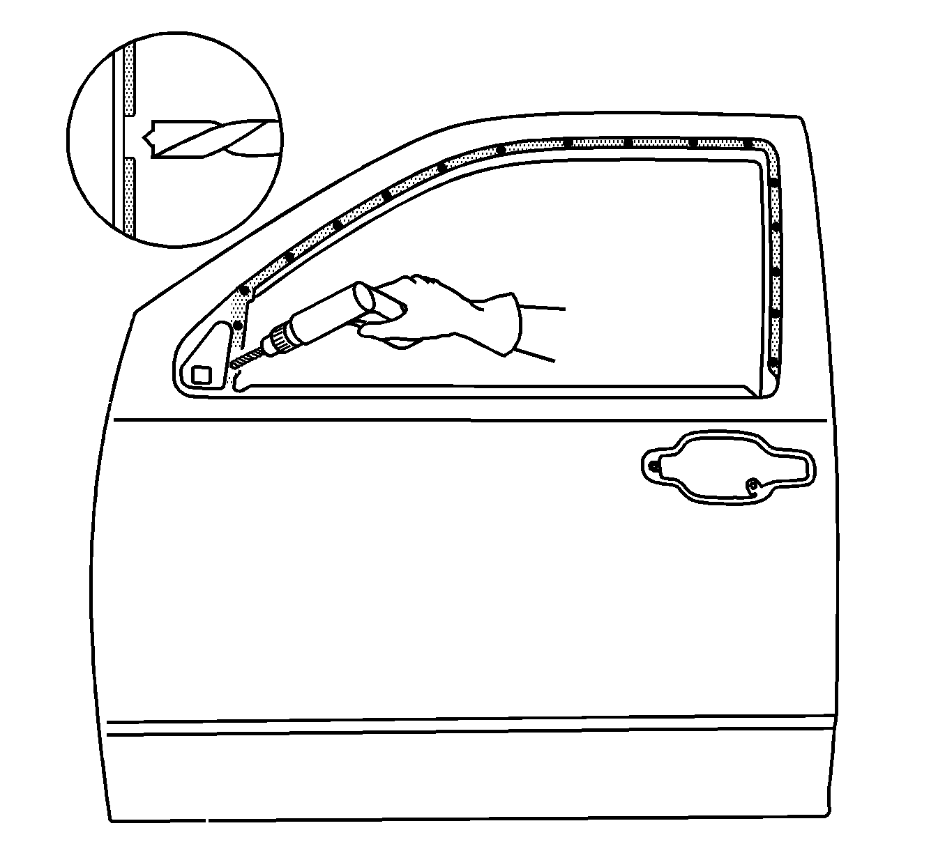
- Apply a 3-6 mm (1/8-1/4 in) bead of metal panel bonding adhesive to both of the mating surfaces.
- Using a small acid brush, spread a coat of adhesive to cover all the bare metal surfaces to ensure corrosion protection.
- Apply a 9-13 mm (3/8-1/2 in) bead of metal bonding adhesive to the mating surfaces of the service panel.
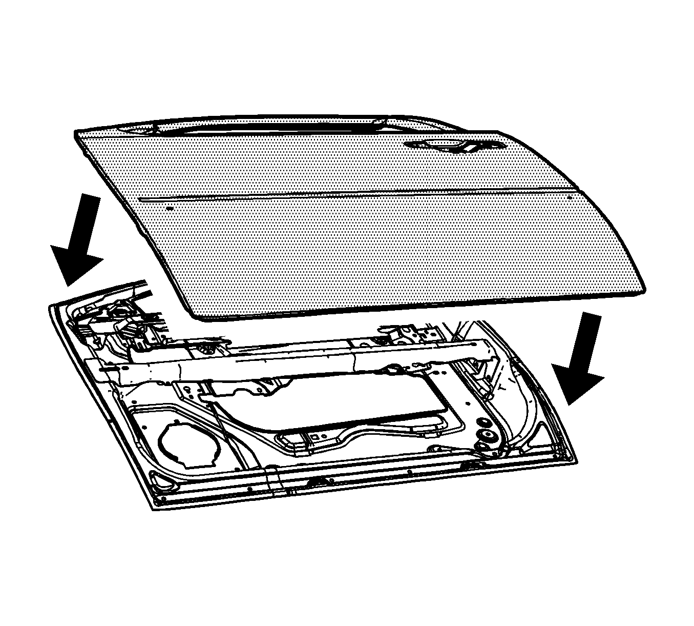
- Install the door outer panel to the door shell.
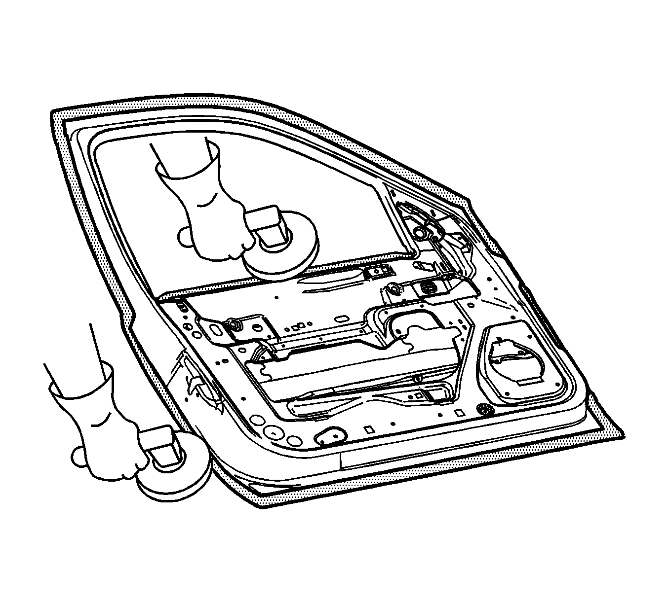
- Clamp the door outer panel into position, as required.
- Using a hammer re-hem the hem flanges around the door shell.
- Using lacquer thinner remove the excess adhesive from the door panel area.
- Install the door to the vehicle. Inspect the door outer panel for proper alignment; then adjust the alignment, as required. Refer to Front Side Door Replacement.
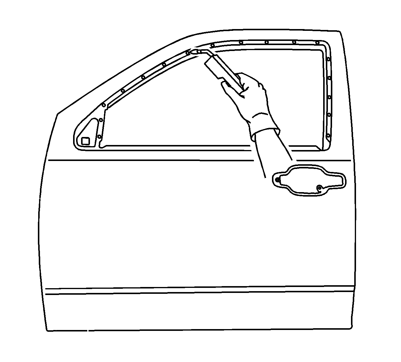
- Using metal-inert gas (MIG), weld the door outer panel to the door frame in the locations noted at the upper door frame.
- Clean and prepare all welded surfaces.
- Apply Fusor super flexible anti-flutter foam-fast set, Fusor P/N 121/124, or equivalent, in a continuous bead the entire length between the beltline reinforcement and the door outer panel.
- Apply Fusor super flexible anti-flutter foam-fast set, Fusor P/N 121/124, or equivalent, in a continuous bead the entire length between the door outer panel and the inner safety beam making multiple passes behind the side impact sensor portion of the beam as required to fill in any gaps.
- Paint the repaired area. Refer to Basecoat/Clearcoat Paint Systems.
- Install all related panels and components.
- Enable the SIR system. Refer to SIR Disabling and Enabling.
- Connect the negative battery cable. Refer to Battery Negative Cable Disconnection and Connection.
Note: In any area damaged beyond recognition, space plug weld holes every 40 mm (1 in) apart.
Note: Do not allow the door to totally cure off the vehicle, as proper alignment of the door outer panel to the door shell will be difficult.
Note: Do NOT pull the panels apart after being joined together. Slide the panels against each other to realign the panels.
Continue to hammer in stages along the hem flanges.