For 1990-2009 cars only
Special Tools
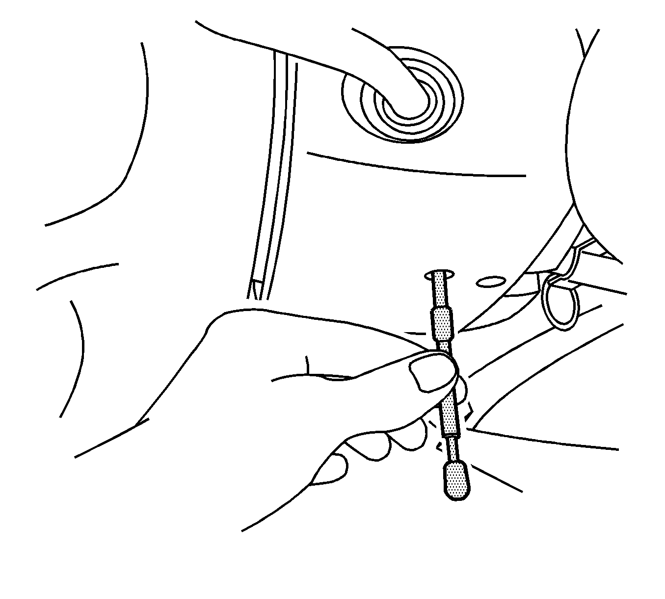
J 42640 Steering Column Anti-Rotation Pin
Removal Procedure
- Install anti-rotation pin J 42640 in the steering column lower access hole.
- Mark the relationships of the following components:
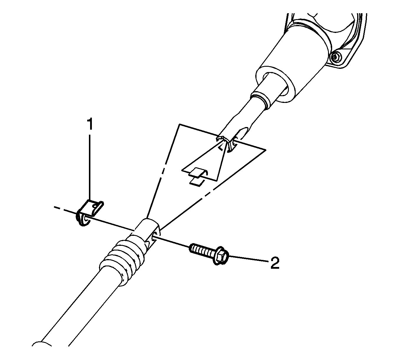
- Remove the steering shaft coupling nut (1) and bolt (2) at the upper intermediate steering shaft.
- Remove the steering column seal. Refer to Steering Column Seal Replacement.
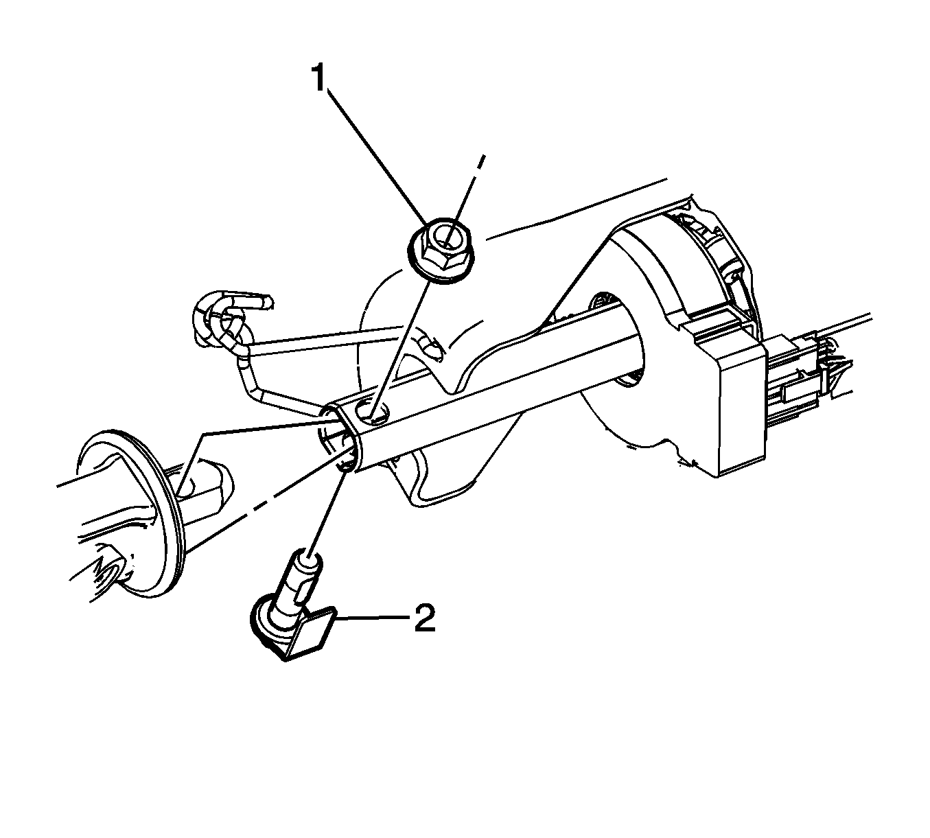
- Remove the steering shaft coupling nut (1) and bolt (2) at the steering column.
- Remove the upper intermediate steering shaft from inside the engine compartment.

Caution: The wheels of the vehicle must be straight ahead and the steering column in the LOCK position before disconnecting the steering column or intermediate shaft from the steering gear. Failure to do so will cause the SIR coil assembly to become uncentered, which may cause damage to the coil assembly.
| 2.1. | Mark the relationship of the upper intermediate steering shaft to the steering column. |
| 2.2. | Mark the relationship of the upper intermediate steering shaft to the steering shaft coupling |


Installation Procedure
- Install the upper intermediate steering shaft from inside the engine compartment.
- Install the steering shaft coupling nut (1) and bolt (2) at the steering column and tighten to 62 N·m (46 lb ft).
- Install the steering column seal. Refer to Steering Column Seal Replacement.
- Install the steering shaft coupling nut (1) and bolt (2) at the steering shaft coupling and tighten to 50 N·m (37 lb ft).
- Remove anti-rotation pin J 42640 from the steering column lower access hole.
Note: If a new steering shaft coupling is being installed then transfer the position of the alignment marks from the old component to the same locations on the new component. Failure to transfer the alignment marks may result in an off-center steering wheel after installation.
Caution: Refer to Fastener Caution in the Preface section.


