Customer Satisfaction-Differential Pinion Gear Washers (GM ODC ONLY)

| Subject: | 04064 - Differential Pinion Gear Washers |
| Models: | 2004 Chevrolet Aveo |
Condition
GMDAT has decided that certain 2004 Chevrolet Aveo model vehicles were built with pinion gear washers that do not meet engineering specifications. The suspect washer can become damage due to stress and be ejected from the differential assembly.
Correction
Dealers are to replace the differential pinion gear washers.
Vehicles Involved
Involved are certain 2004 Chevrolet Aveo model vehicles built within these VIN breakpoints:
Year | Division | Model | From | Through |
|---|---|---|---|---|
2004 | Chevrolet | Aveo | 4B118618 | 4B122494 |
Important: Dealers should confirm vehicle eligibility through GMVIS (GM Vehicle Inquiry System) prior to beginning program repairs. [Not all vehicles within the above breakpoints may be involved.]
Involved vehicles have been identified by Vehicle Identification Number. Computer listings containing the complete Vehicle Identification Number, customer name and address data have been prepared and are being furnished to involved dealers with the program bulletin. The customer name and address data will enable dealers to follow up with customers involved in this program. Any dealer not receiving a computer listing with the program bulletin has no involved vehicles currently assigned.
These dealer listings may contain customer names and addresses obtained from Motor Vehicle Registration Records. The use of such motor vehicle registration data for any other purpose is a violation of law in several states/provinces/countries. Accordingly, you are urged to limit the use of this listing to the follow-up necessary to complete this recall.
Parts Information
Parts required to complete this recall are to be ordered according to procedure.
Part Number | Description | Qty/ Vehicle |
|---|---|---|
96325063 | Washer | 2 |
94535790 | GR Shift Shaft Pin | 1 |
94535793 | Spring Pin | 1 |
94535785 | Inner Pin | 1 |
94535797 | Outer Pin | 1 |
94535142 | Shift Fork Snap Ring | 1 |
94535110 | Fifth Gear Snap Ring | 1 |
94520431 | Screw | 6 |
93740319 | Oil - Transmission (SAE 75W-85, GL4) (1L) | 2 |
93740140 | Antifreeze (Ethylene Glycol) (2L) | 1 |
96568025 | Transaxle | As Required |
Service Procedure
Preparation
- Check all the parts required.
- Check the tools required or recommended.
Differential pinion washer (2 ea), gear shift shaft pin (1 ea), spring pin (1 ea), inner pin (1 ea), outer pin (1 ea), shift fork snap ring (1 ea), fifth gear snap ring (1 ea), fork plug (1 ea), screw (6 ea), manual T/M oil, antifreeze
| • | Input shaft holder (DW220-120): use for holding the input shaft when installing the counter shaft fifth gear nut. |
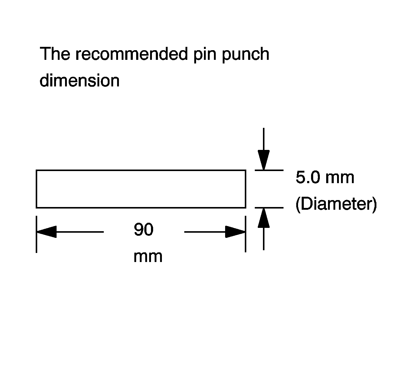
| • | Pin punch: Use for removing the pinion gear pin. |
| • | If proper pin punch is not available in workshop, made an adequate pin put by grinding a nail head. |
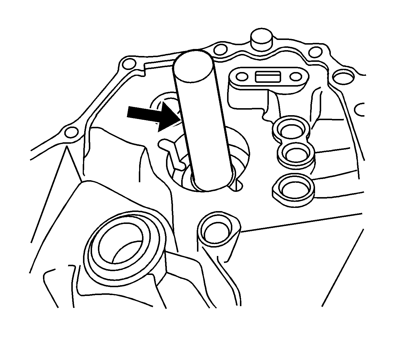
| • | Shaft guide cap: use for avoiding damaging the input shaft oil seal when inserting the gear unit. |
| • | It is recommended that you get any tool equivalent to the cap shown in the illustration from the commercial market. |
Inspection & Removal Procedures
- Raise the vehicle suitably.
- Remove the transmission fluid drain plug and drain the fluid.
- Check if a piece of differential pinion washer or gear teeth are stuck on the drain plug magnetic.
- Remove the manual transaxle. Refer to Five Speed Manual Transaxle. If the assembly removed is stained, clean it by using an air blower.
- Remove the related clutch parts. Refer to Clutch.
- Disconnect the backup light switch and the speedometer.
- Remove the shift interlock bolt.
- Remove the side cover.
- Remove the fifth-gear shift fork guide ball, the snap ring and the input shaft fifth-gear snap ring.
- Remove the fifth-gear shift fork pin.
- Remove the input shaft fifth-gear fork and synchronizer hub assembly.
- Remove the input shaft fifth-gear, the synchronizer ring and the fifth-gear bearing.
- Remove the countershaft fifth-gear.
- Remove the left case plate and the countershaft bearing shim.
- Remove the shift shaft springs and balls.
- Remove the reverse idler gear shaft bolt.
- Remove the transaxle case (left).
- Remove the reverse gear shift lever.
- Remove the reverse idler gear shaft assembly.
- Remove the fifth-reverse gear shift shaft.
- Remove the shift and select lever inner and outer pins.
- Remove the gear shift and select shaft assembly.
- Remove the gear unit.
- Remove the differential assembly.
- Fix the differential assembly to a vise using a protector.
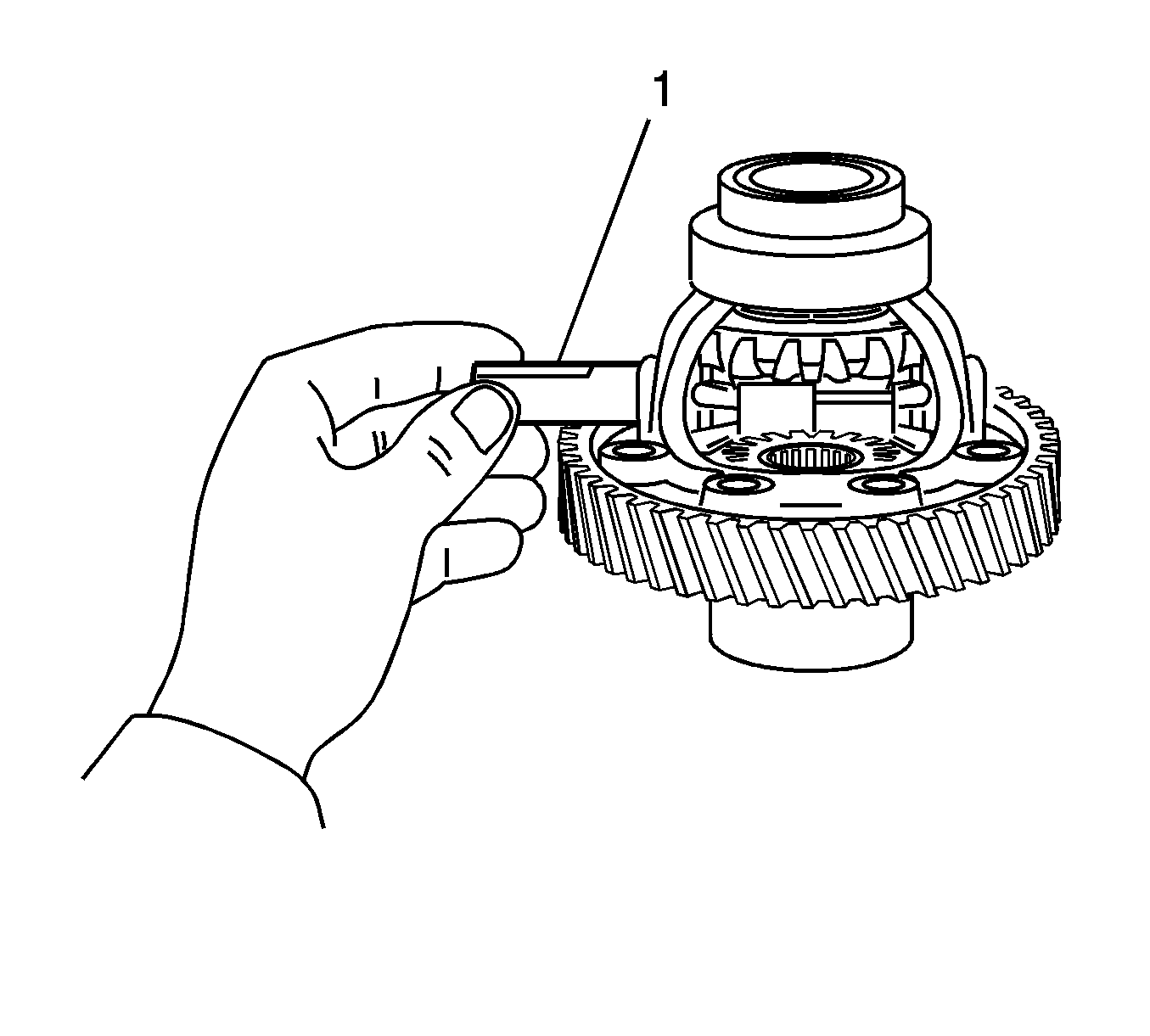
- Remove the pinion gear pin using a pin punch and a hammer.
- Remove the pinion gear shaft from the case (1).
- Remove the pinion gears and the washers (1).
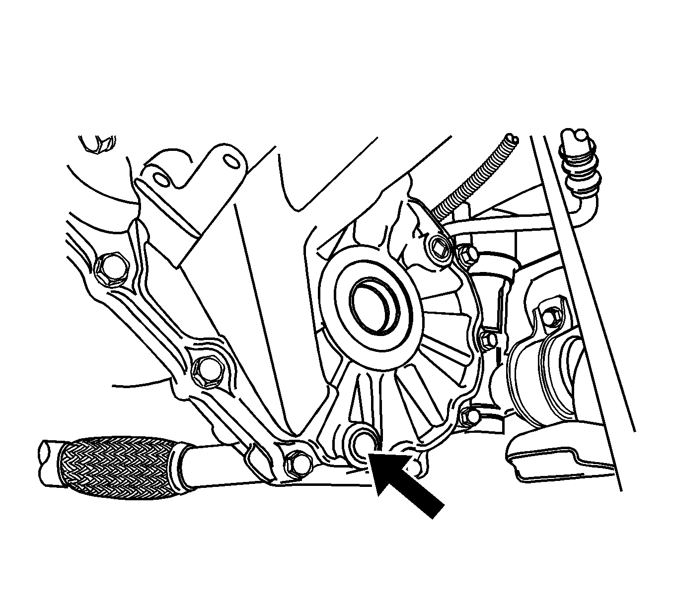
Important:
• If a piece is found, replace the transmission assembly. In this case,
some parts in the transmission were damaged due to the differential pinion gear washers
ejected from the differential assembly. • If no pieces are found, continue with Step 4.
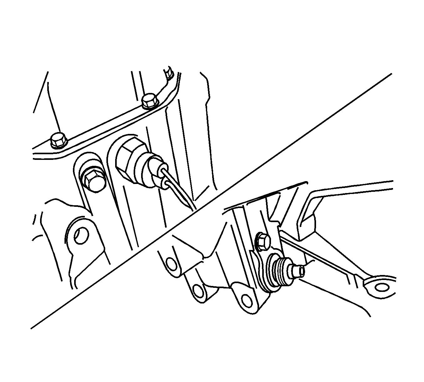
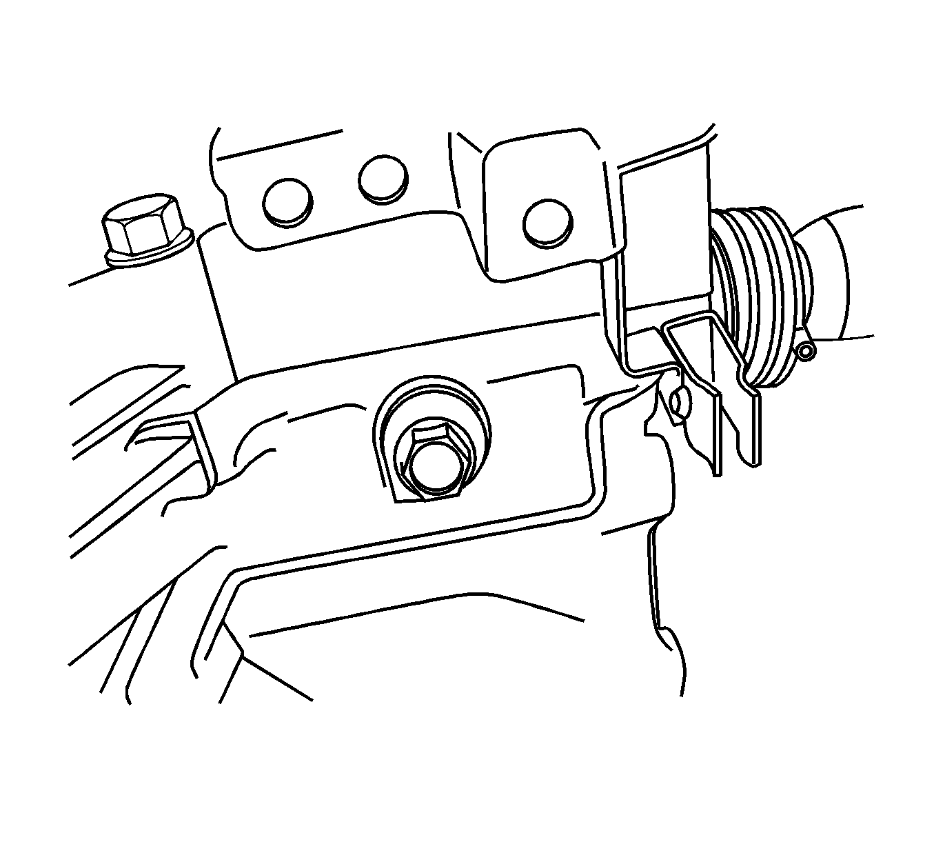
Important: Be sure to remove the shift interlock bolt. Otherwise, the gear shift and shaft assembly cannot be removed.
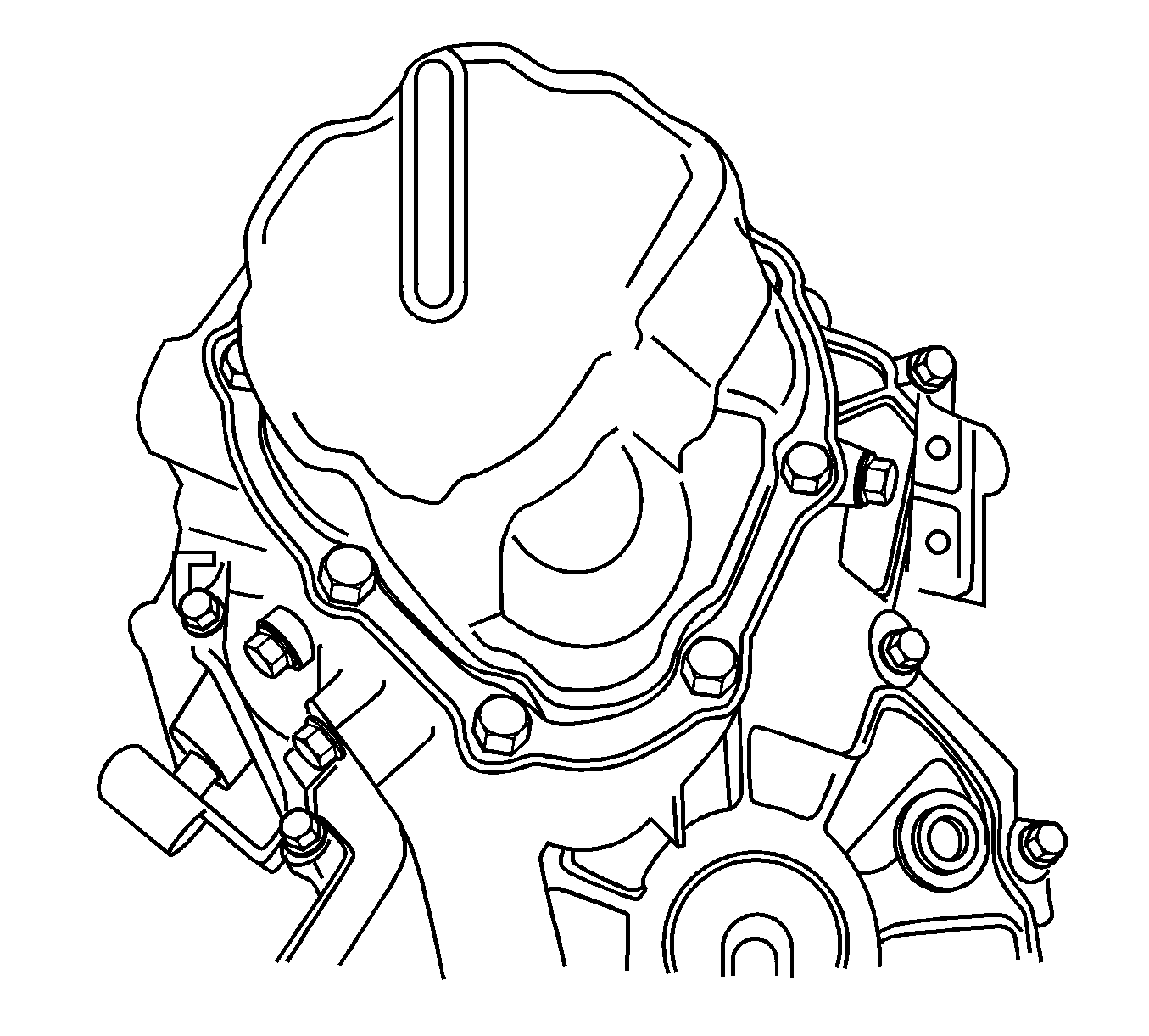
Important: Be careful not to deform the oil pipe when removing the side cover. The deformation of the oil pipe could make a noise due to the interface with the input shaft.
| 8.1. | Remove the bolts. |
| 8.2. | Remove the side cover using a rubber hammer. |
| 8.3. | Remove the sealant on the side cover and the transaxle case. |
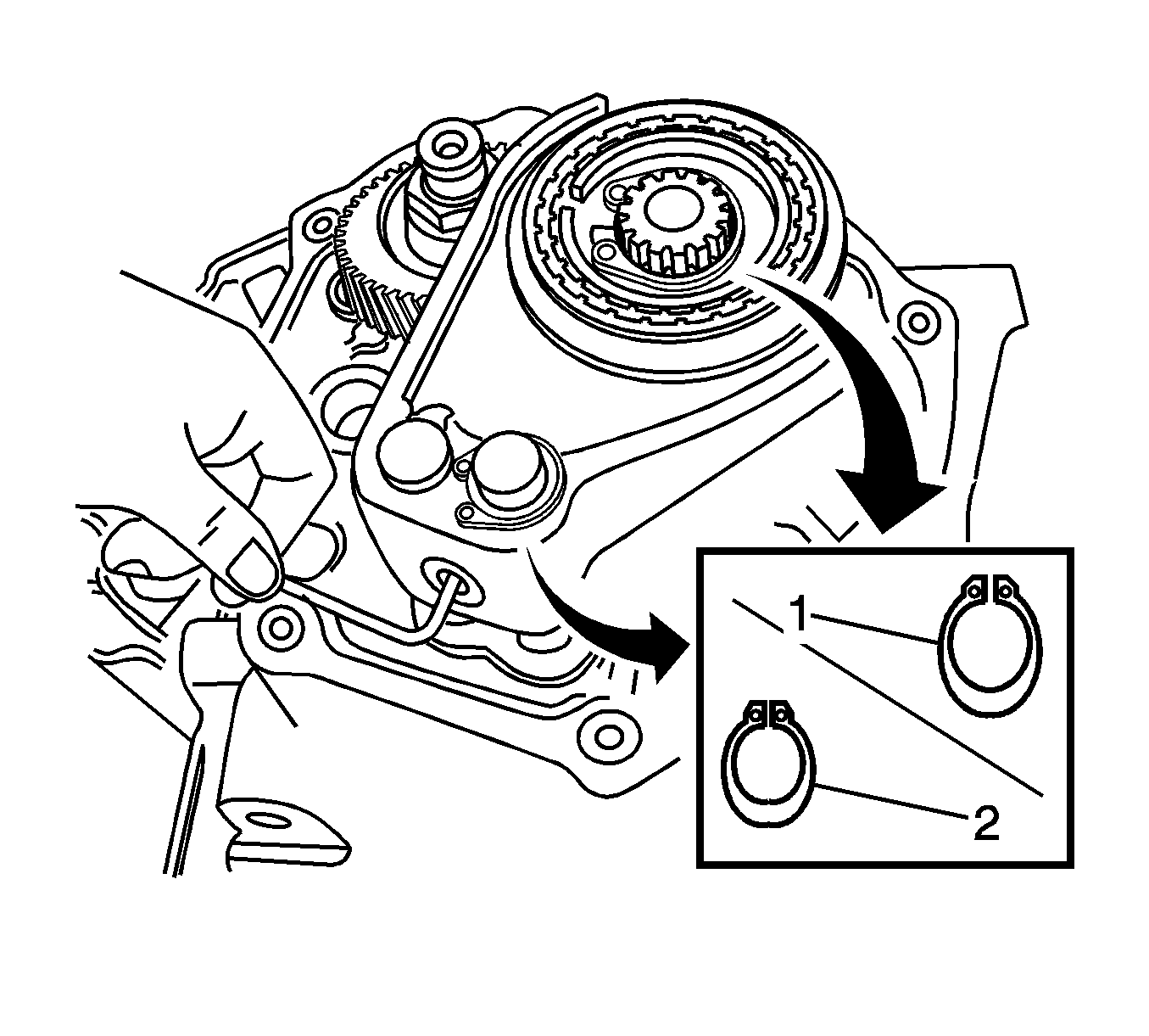
| 9.1. | Remove the fifth-gear shift fork plug. |
| Important: Use a magnetic stick to avoid missing the ball. |
| 9.2. | Remove the guide ball. |
| 9.3. | Remove the fifth-gear shift fork snap ring (2) |
| 9.4. | Remove the fifth-gar snap ring (1). |
| 9.5. | Remove the fifth-gear synchronizer plate. |
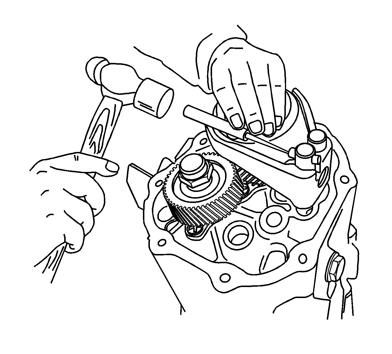
| 10.1. | Shift the shift fork to the fifth-gear. |
| 10.2. | Remove the fork pin using a punch and a hammer. |
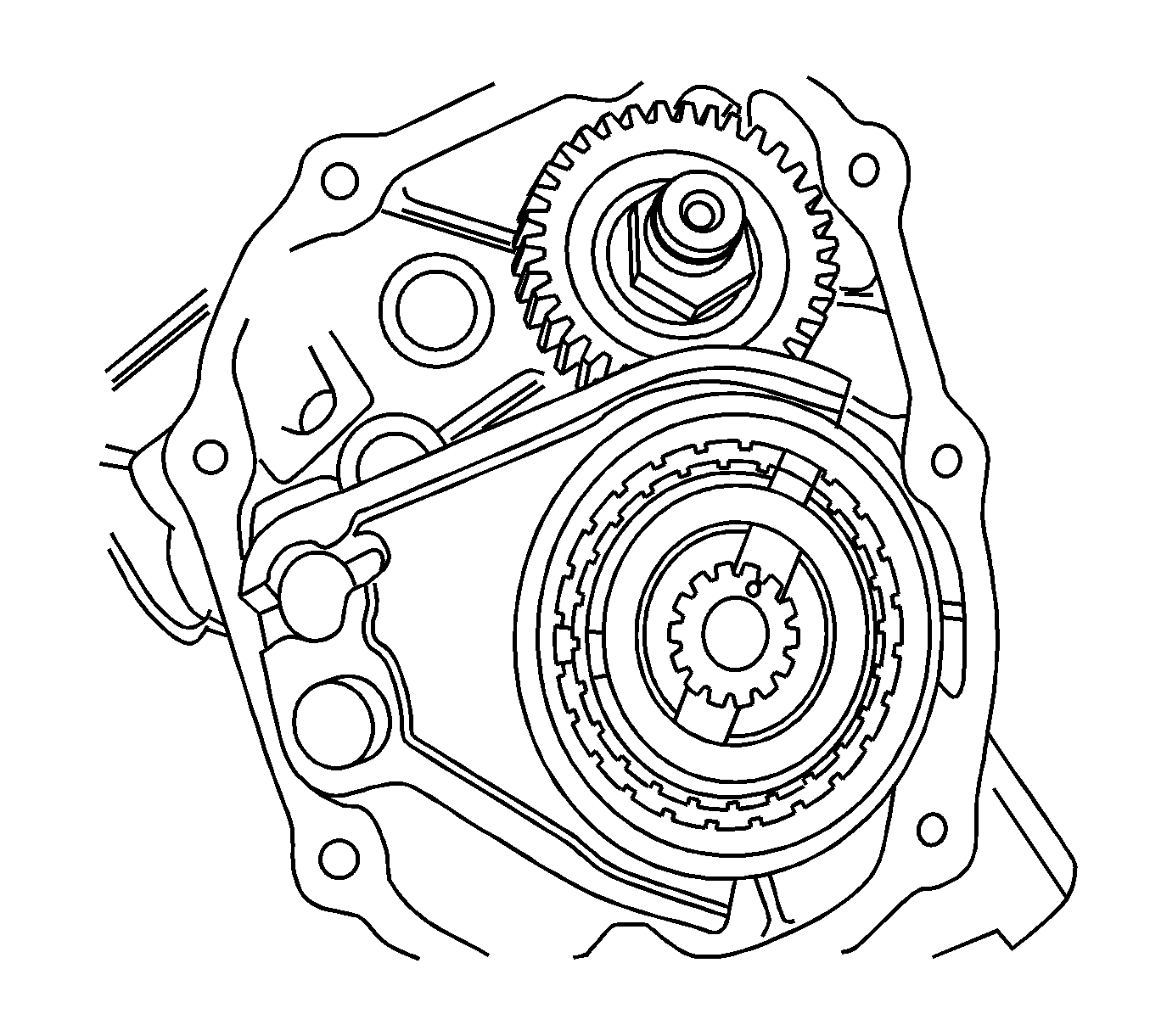
| 11.1. | Pull and remove the fork and the hub assembly together (1). |
| 11.2. | Remove the sleeve, key and spring from the synchronizer hub assembly. |
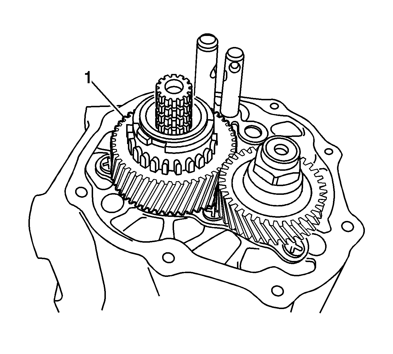
| 12.1. | Pull and remove the fifth-gear, wave spring and synchronizer ring together (1). |
| 12.2. | Remove the fifth-gear bearing. |
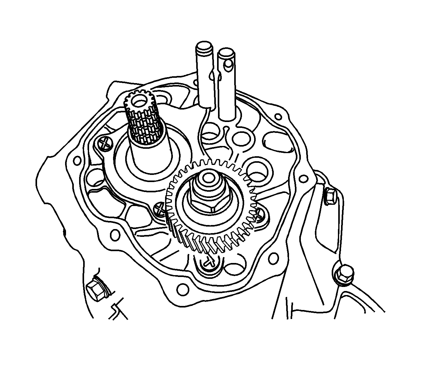
Remove the caulking and the nut.
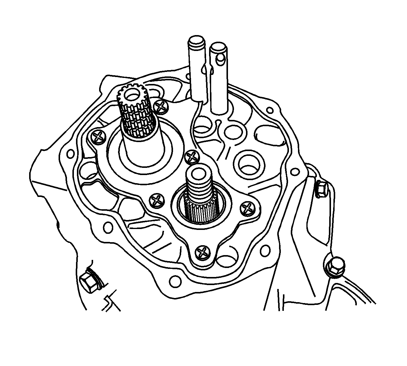
| Important: To prevent damage of the screw head during removal of the screws, use an impact driver. |
| 14.1. | Remove the screws. |
| 14.2. | Remove the left case plate. |
| 14.3. | Remove the countershaft bearing shim. |
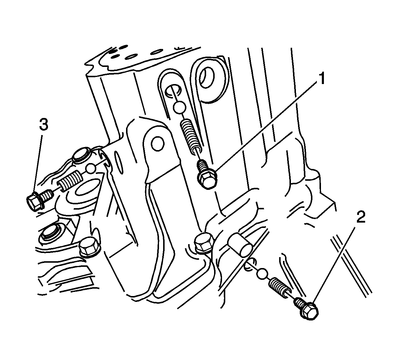
| Important: There is a difference between the fifth reverse gear shift shaft spring and the others. Mark them to distinguish easily when installing. Use a magnetic stick to avoid missing the ball. |
| 15.1. | Remove the bolt and the fifth-reverse gear shift shaft spring and ball (2). |
| 15.2. | Remove the bolt and the third-fourth gear shift shaft spring and ball (1). |
| 15.3. | Remove the bolt and the first-second gear shift shaft spring and ball (3). |

Important: The case (left) cannot be removed without removing the reverse idler gear shaft bolt.

| 17.1. | Remove the bolts from the left side case. |
| 17.2. | Remove the bolts from the right side case. |
| 17.3. | Remove the left side case by hitting with a rubber hammer lightly. |
| 17.4. | Remove the sealant on the case. |
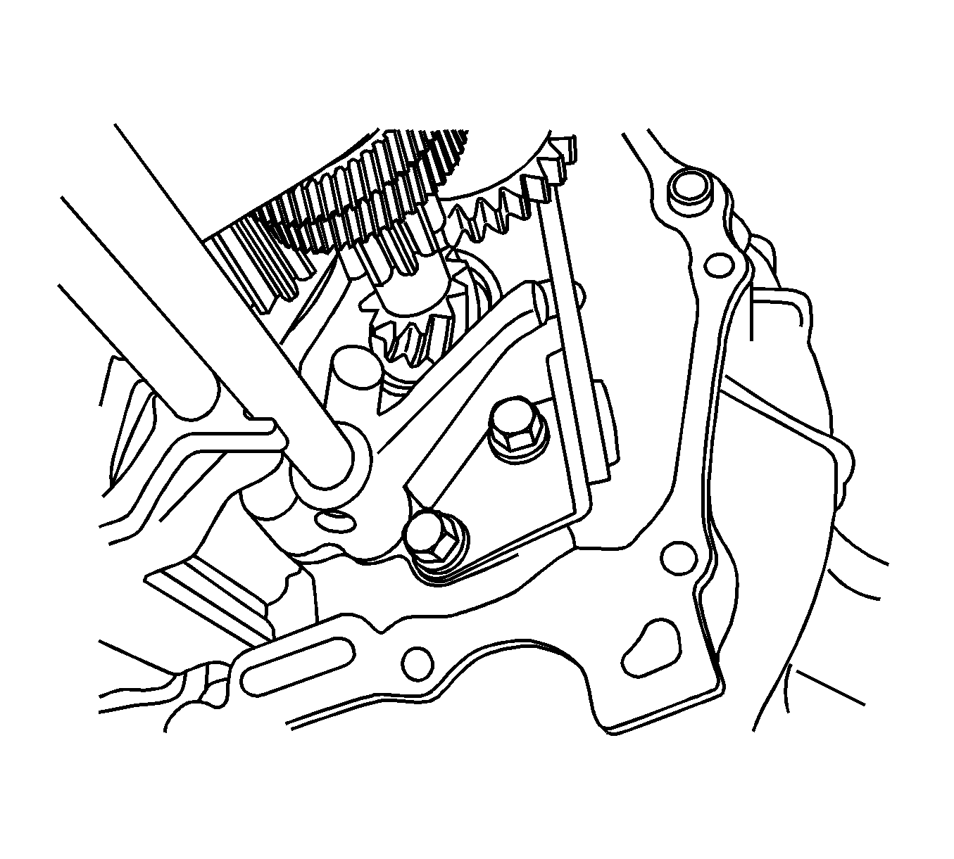
| 18.1. | Remove the bolts. |
| 18.2. | Remove the reverse gear shift lever. |
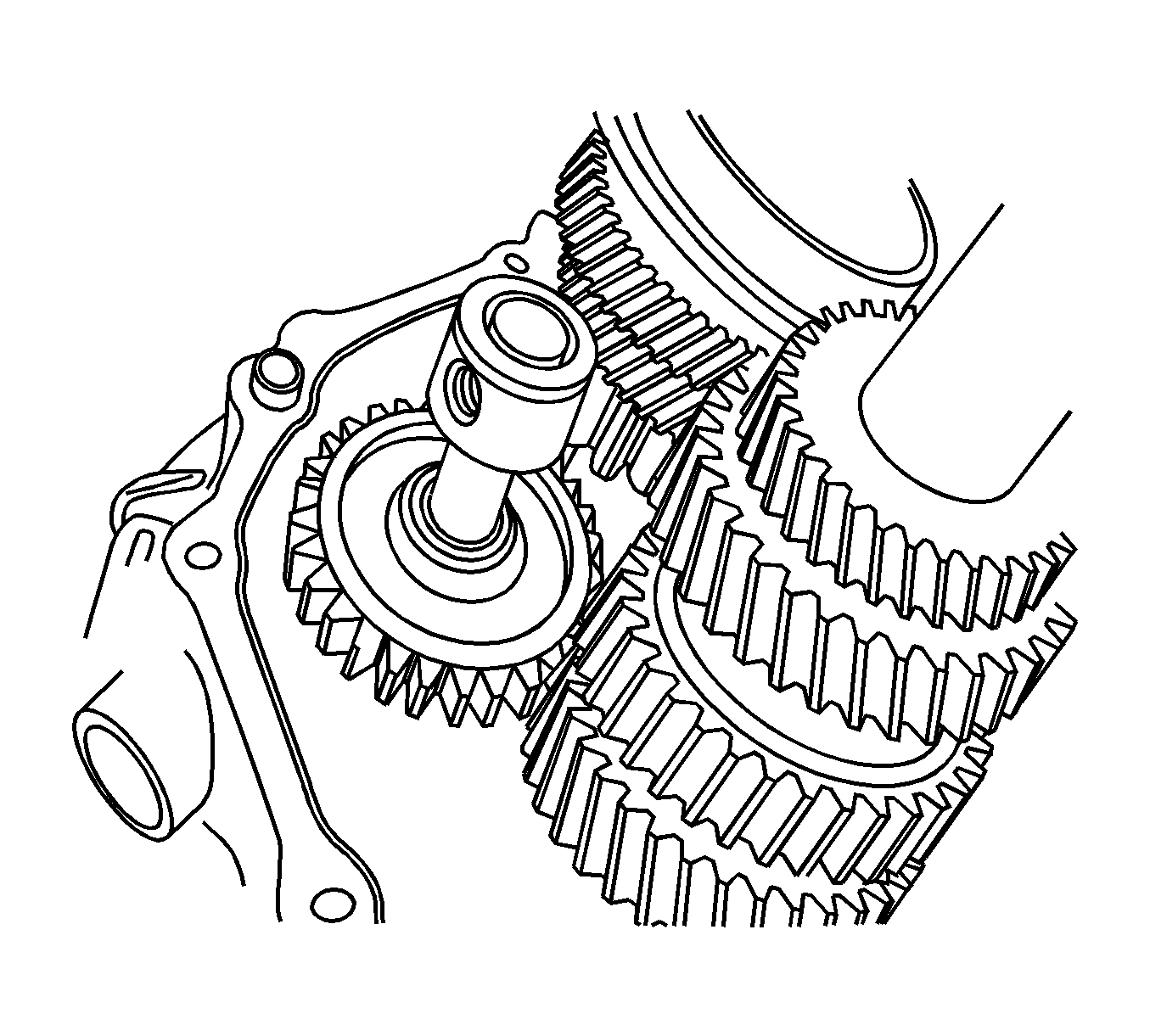
| 19.1. | Push the reverse idle gear toward the inner case. |
| 19.2. | Pull the shaft and remove the reverse idle gear and shaft. |
| 19.3. | Remove the reverse idle gear from the shaft. |
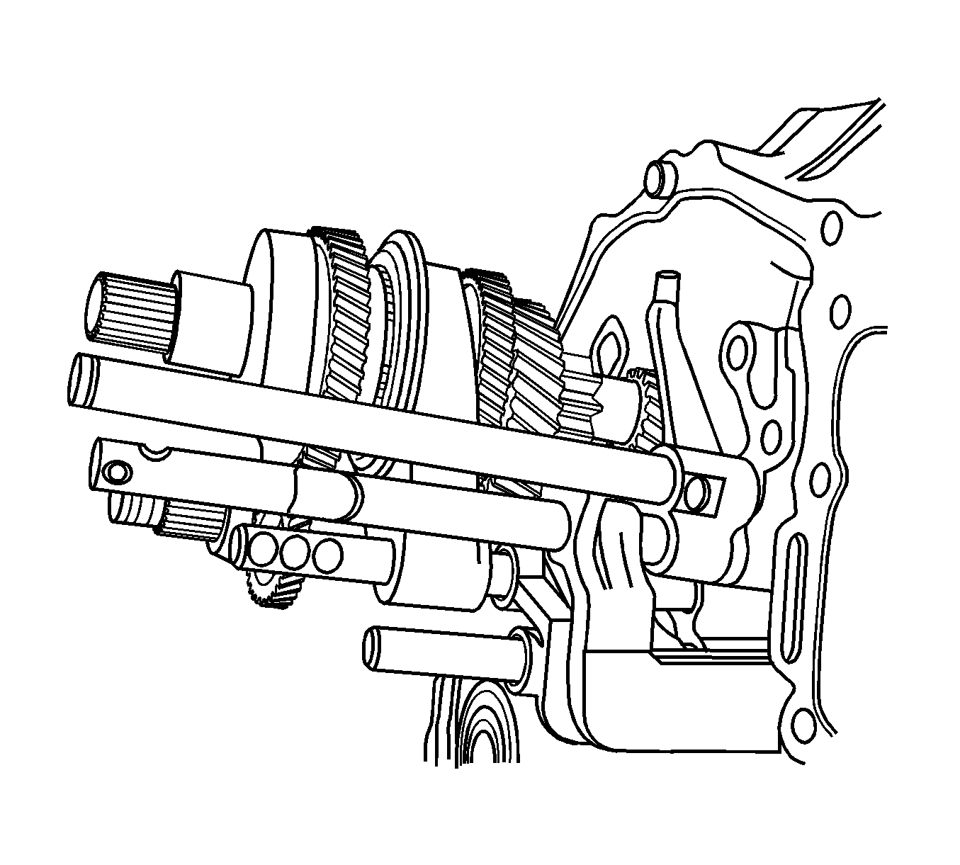
Important: Press the gear shift and select lever towards first and second gear to remove the fifth-reverse gear shift shaft.
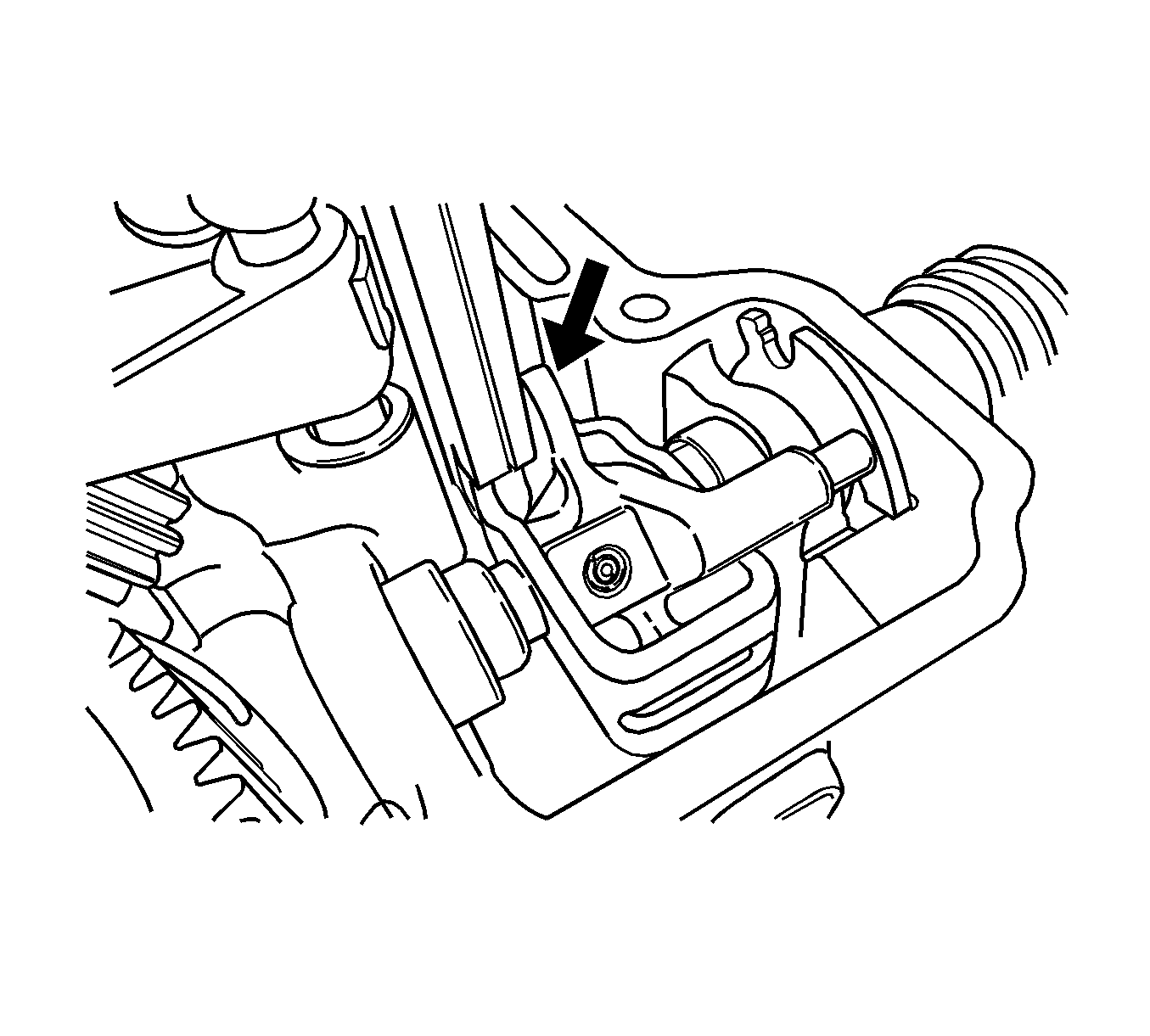
Important: Pull the gear shift and select lever (1) towards fifth-reverse gear and rotate the shift and select shaft about 45 degrees.
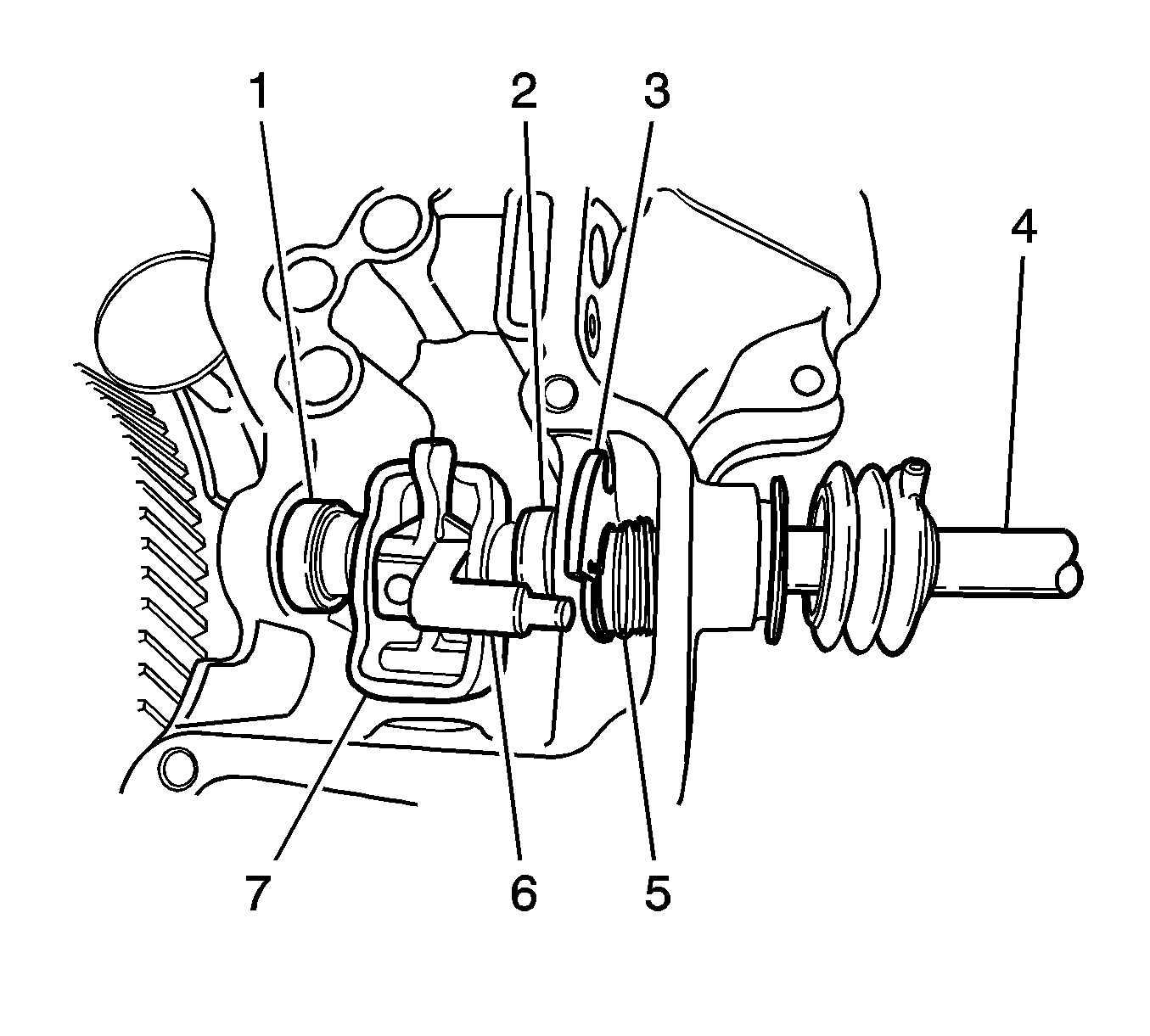
| 22.1. | Remove the shift and select shaft (4). |
| 22.2. | Remove the gear select spring assemblies (1). |
| 22.3. | Remove the gear shift interlock plate (7). |
| 22.4. | Remove the gear shift lever (6). |
| 22.5. | Remove the fifth and reverse gear shift cam (3). |
| 22.6. | Remove the return spring (5). |
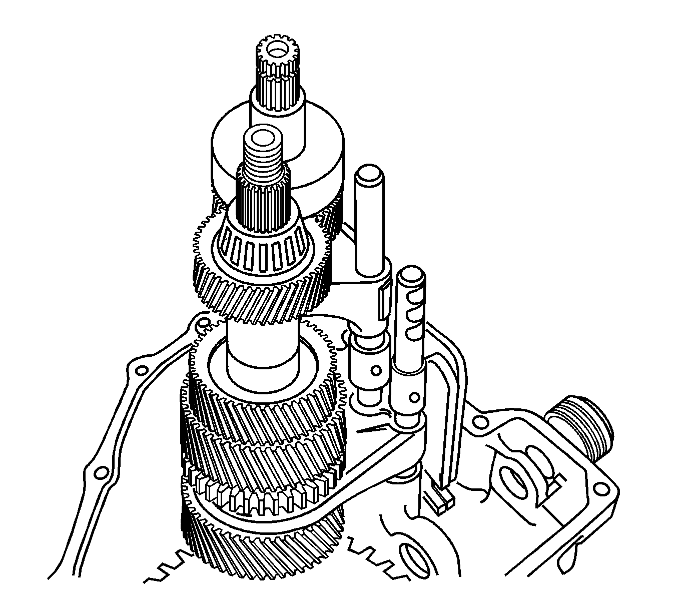
Notice: Be careful not to damage the teeth of the countershaft pinion and the differential ring gear.
The gear unit and the shift shaft assembly must be removed together.

| 24.1. | Insert a wooden stick into the lower side of the differential. |
| 24.2. | Remove the differential assembly by moving it right and left. |
| 24.3. | Remove the countershaft RH bearing. |
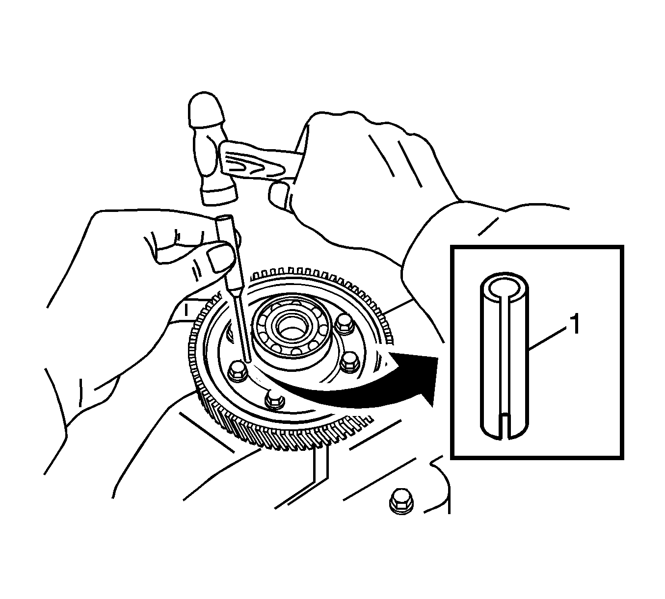

Important: In case the proper pin punch is not available, make an adequate pin punch by grinding a nail head. The recommended diameter and length of the pin punch are 5.0 mm and 90 mm, respectively.
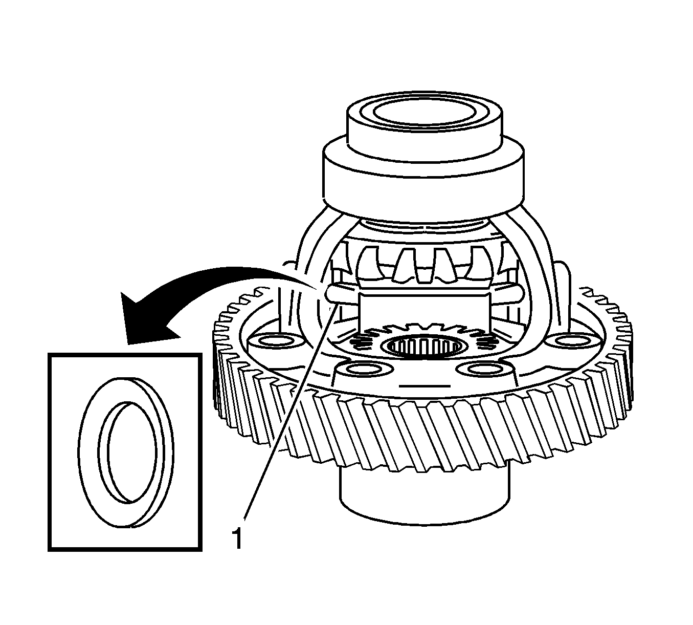
Important: Remove the pinion gears and the washers by rotating the side gears.
Installation Procedures
- Install the pinion gears and the washers.
- Install the pinion shaft and the pin.
- Install the differential assembly to the right side of the transaxle case.
- Install the gear unit by matching it with the input and the countershaft hole.
- Install the fifth-reverse gear shift shaft.
- Install the fifth-reverse gear shift shaft ball and spring.
- Install the reverse idler gear shaft assembly (1) and the reverse gear shift lever.
- Install the gear shift and select shaft assembly.
- Install the shift and select lever inner and outer pins.
- Tighten the interlock bolt a little bit.
- Install the transaxle left side case to the transaxle. Coat the transaxle case with the recommended sealant (Three Bond 1215).
- Install the first-second gear shaft ball and spring.
- Install the third-fourth gear shaft ball and spring.
- Install the reverse idle gear shaft bolt.
- Install the countershaft bearing shim.
- Install the left case plate and the countershaft fifth gear.
- Install the input shaft fifth gear bearing and the fifth/synchronizer ring.
- Install the fifth gear fork to they synchronizer hub assembly.
- Install the fifth gear fork and the synchronizer hub assembly to the input shaft.
- Install the fifth gear shift fork pin.
- Install the input shaft fifth gear snap ring, the fifth gear shift fork snap ring and the guide ball.
- Install the countershaft fifth gear nut.
- Install the side cover. Coat the side cover with the recommended sealant (Three Bond 1215).
- Install the shift interlock bolt.
- Install the backup light switch and the speedometer driven gear assembly.
- Install the related clutch parts. Refer to Clutch.
- Install the manual transaxle. Refer to Five-Speed Manual Transaxle.
Important: Install the pinion gears and the washers simultaneously.

Important: Use only a new pin.
Insert the shaft into the gear pin hole by rotating (1).

Install the countershaft RH bearing.

Important: Be careful not to damage the teeth of the countershaft pinion and the differential ring gear. Be careful not to damage the input shaft oil seal when inserting the gear unit by using the guide cap (recommended in Steps 2 of Preparation) if possible because the end of the shaft could damage the oil seal.

Important: Install the fifth-reverse gear shift shaft spring marked when removing.
Tighten
Tighten the bolt to 10-16 N·m (7-12 lb ft).
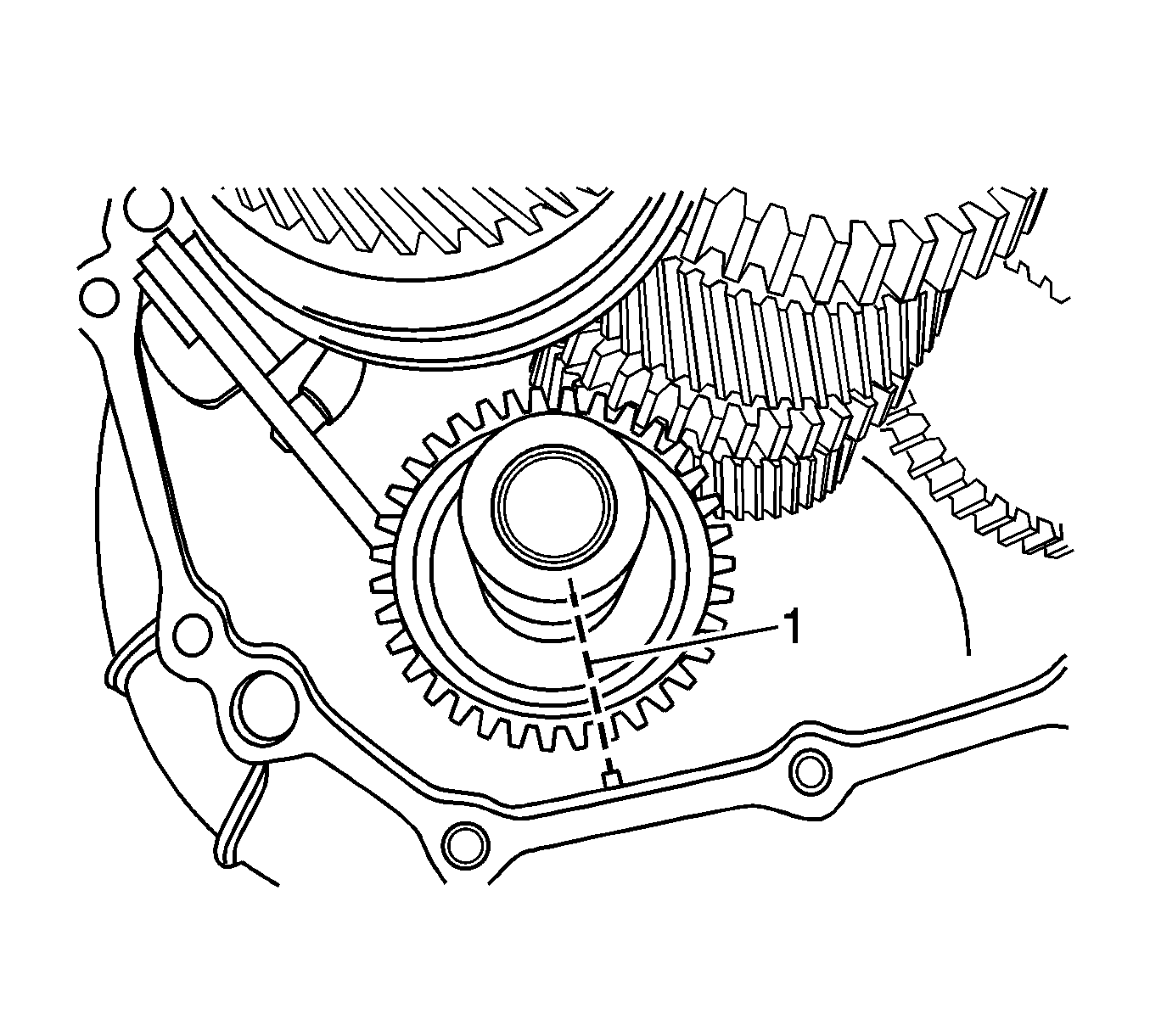
Important: Match the marking on the reverse idle gear shaft bolt hole with the protrusion of the transaxle case (right side).
Tighten
Tighten the bolts to 18-28 N·m (13-21 lb ft).

| 8.1. | Install the shift and select shaft oil seal. |
| 8.2. | Install the gear select spring assemblies. |
| 8.3. | Install the gear shift interlock plate. |
| 8.4. | Install the gear shift lever. |
| 8.5. | Install the fifth and reverse gear shift cam. |
| 8.6. | Install the return spring. |
| 8.7. | Install the shift and select shaft. |

Important: When installing the inner and outer pins, the crevices of the two pins must be symmetrical with each other.
Use only new inner and outer pins.
Important: If the bolt could not be inserted, alignment between the interlock plate hole and the bolt could not be matched.

Tighten
Tighten the bolts to 15-22 N·m (11-16 lb ft).
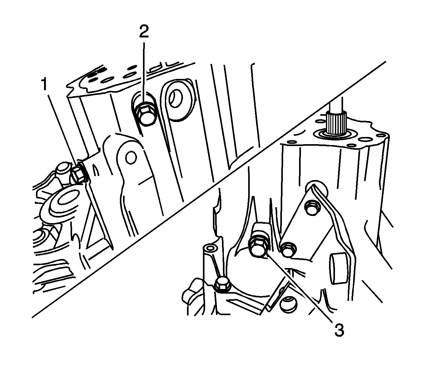
Tighten
Tighten the bolt to 10-16 N·m (7-12 lb ft)
(1).
Tighten
Tighten the bolt to 10-16 N·m (7-12 lb ft)
(2).
Tighten
Tighten the bolt to 18-28 N·m (13-21 lb ft)
(3).


Important: Position the machined boss side toward the side cover plate.
Important: Use only new screws.
Tighten
Tighten the screws to 6-7 N·m (53-62 lb in).

| 17.1. | Insert the bearing into the input shaft. |
| 17.2. | Install the fifth gear, synchronizer ring and wave spring matching synchronizer's oil groove and input shaft punched mark (1). |

Important: Position the longer boss side of the hub toward the inner side and match the synchronizer key and the hub groove with the input shaft punched mark.

Important: Use only a new shift fork pin.
| 20.1. | Push the shift fork toward the fifth gear. |
| 20.2. | Install the shift fork pin using a pin punch and a hammer. |

Important: Use only new snap rings and fork plug.
| 21.1. | Install the fifth gear synchronizer plate. |
| 21.2. | Install the fifth gear snap ring (3). |
| 21.3. | Install the fifth gear shift fork snap ring (2). |
| 21.4. | Install the guide ball. |
| 21.5. | Install the fifth gear shift fork plug (1). |
Tighten
Tighten the fifth gear shift fork plug to 10-18 N·m
(7-13 lb ft).
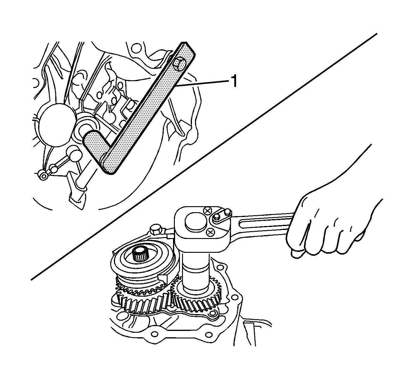
| 22.1. | Push the shift fork toward the fifth gear. |
| 22.2. | Hold the input shaft using the input shaft holder DW220-120 (1). |
Tighten
Tighten the fifth gear nut to 60-80 N·m
(44-59 lb ft).
| 22.3. | Caulk the nut using a chisel and a hammer. |

Tighten
Tighten the side cover bolts to 8-12 N·m
(71-106 lb in).

Tighten
Tighten the shift interlock bolt to 18-28 N·m
(13-21 lb ft).

Tighten
| • | Tighten the backup light switch nut to 15-18 N·m (11-13 lb ft). |
| • | Tighten the speedometer driven gear assembly bolt to 4-7 N·m (35-62 lb in). |
Claim Information
Submit a Product Program Claim with the information indicated below.
Repair Performed | Part Count | Part No. | Parts Allow | CC-FC | Labor Op | Labor Hours* |
|---|---|---|---|---|---|---|
Replace Pinion Gear Washers | 2 | 96325063 | ** | MA-96 | V1206 | 4.9 |
Replace Transmission | 1 | 96568025 | ** | MA-96 | V1207 | 3.4 |
* -- For Program Administrative Allowance, add 0.1 hours to the "Labor Hours". ** -- The "Parts Allowance" should be the sum total of the current GMDAT Dealer net price plus applicable Mark-Up or Landed Cost Mark-Up for parts needed to complete the repair. | ||||||
Refer to the General Motors WINS Claim Processing Manual for details on Product Recall Claim Submission.
Dealer Program Responsibility
All unsold new vehicles in dealers' possession and subject to this program MUST be held and inspected/repaired per the service procedure of this program bulletin BEFORE customers take possession of these vehicles.
Dealers are to service all vehicles subject to this program at no charge to customers, regardless of mileage, age of vehicle, or ownership, from this time forward.
Customers who have recently purchased vehicles sold from your vehicle inventory, and for which there is no customer information indicated on the dealer listing, are to be contacted by the dealer. Arrangements are to be made to make the required correction according to the instructions contained in this bulletin. This could be done by mailing to such customers a copy of the customer letter accompanying this bulletin. Program follow-up cards should not be used for this purpose, since the customer may not as yet have received the notification letter.
In summary, whenever a vehicle subject to this program enters your vehicle inventory, or is in your dealership for service in the future, you must take the steps necessary to be sure the program correction has been made before selling or releasing the vehicle.
